0
\$\begingroup\$

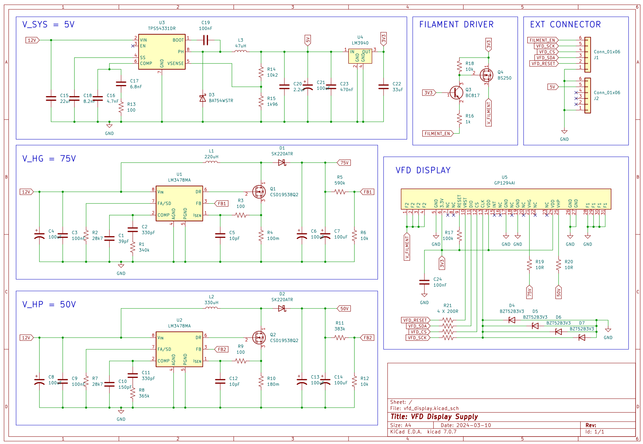
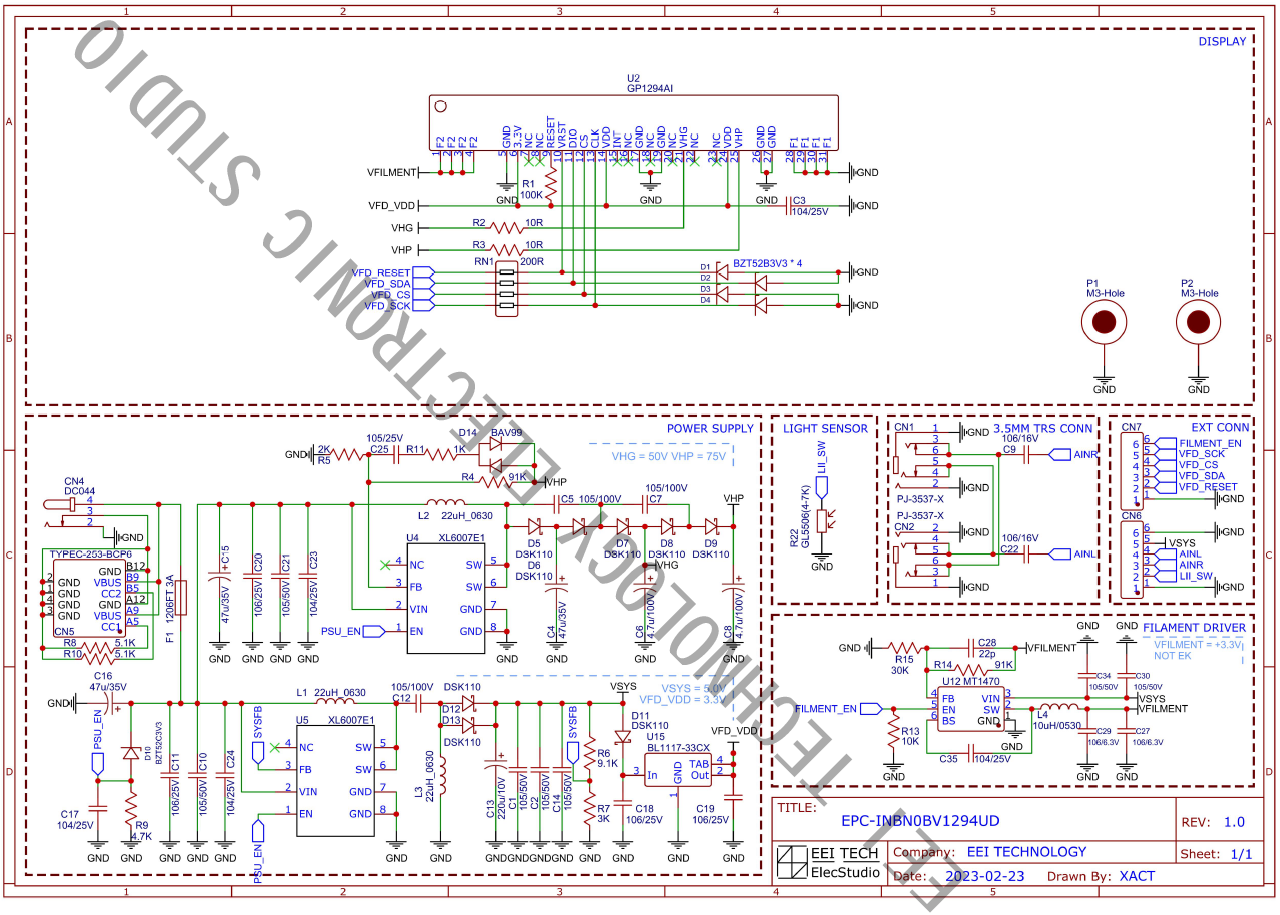
I recently ordered a GP1294AI VFD display from Aliexpress. Unfortunately it did not contain the necessary power supply to power the display, but the datasheet did include the necessary schematics for a power supply.

However, the components used in the schematic are not available from European retailers. This is why I recreated the schematic using different components. I made a few adjustments and wanted to make sure I made no mistakes before starting on the PCB layout as my power electronics knowledge is limited.

  • I will use a 12V supply, so I removed the USB input connector
  • I will not use the aux inputs or light sensor so these were removed
  • The DCDC boost converters creating 75V and 50V were designed using the online WEBENCH tool from Texas Instruments
  • The circuit from the datasheet contains a seperate SMPS for generating 3V3 from 5V. I removed this one as 3V3 is already created by a linear regulator. A high-side switch enabled/disables the filament driver instead.

Adjusted VFD Display Power Supply Datasheet VFD Display Power Supply

All feedback appreciated!

\$\endgroup\$
0

1 Answer 1

1
\$\begingroup\$

Few things I noticed:

  • The diodes on bottom-right (VFD section) should connect to each 200R to the left, instead of having all paralleled across CLK pin.
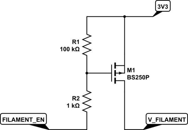
  • The connection of the PMOS that is supposed to be used to switch the V_FILAMENT is wrong. It's upside down so the body diode will always be in forward bias which means V_FILAMENT will always be present regardless of FILAMENT_EN signal status. Plus, if the FILAMENT_EN signal is a 3.3V logic signal then the Q3 can be omitted:

schematic

simulate this circuit – Schematic created using CircuitLab

The circuit from the datasheet contains a seperate SMPS for generating 3V3 from 5V. I removed this one as 3V3 is already created by a linear regulator.

  • It's not that simple. There must be a reason why they used a separate regulator for V_FILAMENT. For example, the current consumption could be higher than the current that the linear regulator can handle. I can see they used BL1117-33CX which is a 3V3/1A regulator, quite similar to the one you have, LM3940. They used the output for VFD as VFD_VDD but they didn't use the same voltage for V_FILAMENT. Instead, they built a 3.3V/2A synchronous buck for V_FILAMENT. So you should consider a separate regulator with similar specs anyways.

I'll update the post as I find some more things.

\$\endgroup\$

Your Answer

By clicking “Post Your Answer”, you agree to our terms of service and acknowledge you have read our privacy policy.

Not the answer you're looking for? Browse other questions tagged or ask your own question.