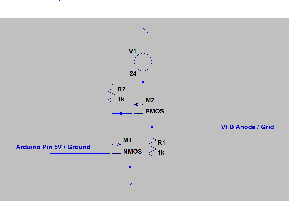
I am trying to operate an IVL2-7/5 vacuum-fluoresecence-display with an Arduino Uno. It is a multiplexed 4 digit clock display that requires a cathode voltage of 2.4V and an anode and grid voltage of 24V. The 24V will be supplied by a seperate voltage source, the Arduino shall simply switch this voltage. (I know that VFD driver ICs exist but I want to try to do this with discrete components)
I have created this circuit, a high side-switch from two MOSFETS, but am unsure weither it's suitable.

My question is basically: Is this circuit a working switch and would it work to switch the 24V supply of a single anode element?
Also: what resistances should I select for R1 and R2? Do I need another resistor between Arduino and M1? I am very inexperienced in electronics, but I vaguely recall that a MOSFET's gate acts kind of like a capacitor and can pull strong currents if switched quickly. I'd like to utilise stronger resistors for R1 and R2 to minimize the current they "consume", but don't know if that will still allow fast enough switching for multiplexing of the VFD.

