0
\$\begingroup\$


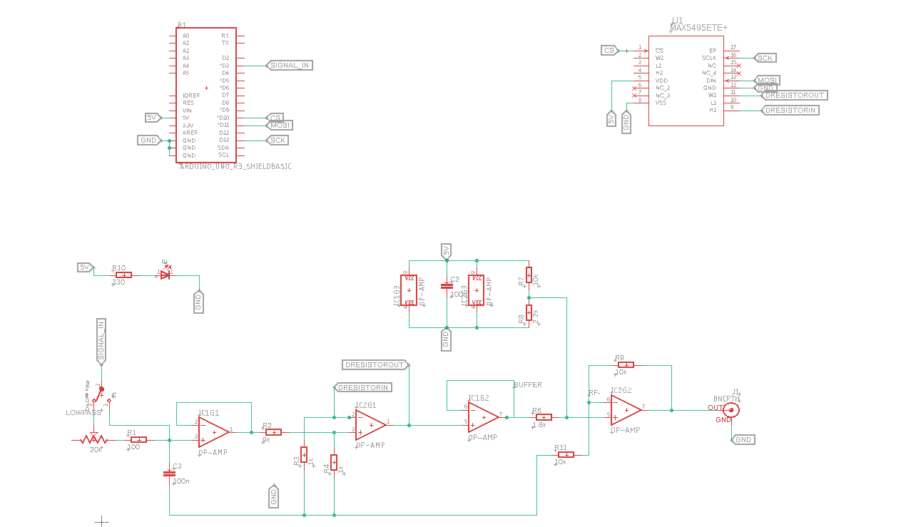
I've designed a circuit to generate a smoothed PWM signal using an Arduino, which then undergoes attenuation, amplification via a non-inverting op-amp, and finally has an approximate offset of 0.9V added. The circuit also includes a digital potentiometer intended to adjust the signal amplitude, but despite assembly and verification, the potentiometer's resistance remains fixed and unresponsive to control attempts.

Circuit Overview: Schematico

PWM Generation: Direct from Arduino.
Smoothing: Via an RC filter.
Attenuation: Using a voltage divider.
Amplification: Through a non-inverting op-amp.
Offset Addition: Approximately 0.9V.

Issue: The digital potentiometer does not adjust as intended, seemingly locked at a specific resistance value. I have meticulously checked the soldering under a microscope and verified connections with a multimeter, finding no apparent issues. This leads me to suspect a potential design flaw or the MAX5495 is wrongly soldered because it's an SMD and i can't be 100% sure the pins are correctly soldered.

Additional Details:

I've developed and assembled the PCB based on this design. The code controlling the potentiometer was sourced from a forum, implying its reliability.

Code Snippet from Arduino forum

MAX5495 Resource page.

MAX5494-MAX5499 Datasheet.
.

My Code:

#include <SPI.h>
const uint8_t CSpin = 10;

void setup() {
    setupSPI();
    setupPWM();
    Serial.begin(115200);
}

void loop() {
    for(uint16_t i = 0; i < 1024; i++) { // Loop over the full range of the digipot
        update_digipot(0x01, i); // Update wiper position
        delay(100); // Short delay between updates for visibility
    }
    delay(1000); // Wait for 1 second after completing a full range update
}


void update_digipot(uint8_t reg, uint16_t value) {
  union {
    uint16_t val;
    uint8_t bytes[2];
  } in;

  in.val = value << 6; //as per datasheet

  digitalWrite(CSpin, LOW);

  //Write Wiper Register.  0x01: wiper1, 0x02: wiper2
  SPI.transfer(reg);

  //send upper value byte
  SPI.transfer(in.bytes[1]);

  //send lower value byte
  SPI.transfer(in.bytes[0]);
  digitalWrite(CSpin, HIGH);
}


void setupPWM() {
    analogWrite(3, 30); // Set PWM to 50% duty cycle on pin D3
}

void setupSPI() {
    pinMode(CSpin, OUTPUT);
    pinMode(3, OUTPUT);
    SPI.begin();
} 
\$\endgroup\$
6
  • 1
    \$\begingroup\$ Test the PCB with a multimeter or PCB tester. There maybe a manufacturing error. \$\endgroup\$
    – liaifat85
    Commented Mar 21 at 15:28
  • 1
    \$\begingroup\$ You have ground missing off your circuit. Your circuit could be made far easier to read as well. \$\endgroup\$
    – Andy aka
    Commented Mar 21 at 15:47
  • 1
    \$\begingroup\$ Related to Andy's comment, it seems you have an unconnected GND label just floating below R2, where does that belong? Using a conventional circuit ground symbol to mark the ground nodes would help clarify the schematic, rather then searching for written out labels. \$\endgroup\$
    – Nedd
    Commented Mar 22 at 5:00
  • 1
    \$\begingroup\$ Does your original code contain the #include <SPI.h> line? Were there any errors when compiling your code? Recheck that pin 1 of the MAX5495 is orientated correctly. Carefully recheck for any solder shorts on adjacent pins. \$\endgroup\$
    – Nedd
    Commented Mar 22 at 6:33
  • \$\begingroup\$ The floating ground is linked on it's nearest net, the bottom one, those are just net labels, i didnt use the symbol i usually just stick with labels and classes \$\endgroup\$ Commented Mar 22 at 11:17

1 Answer 1

1
\$\begingroup\$

Thank you to everyone who took the time to provide insights and advice on my issue with the digital potentiometer in my circuit design. I'm pleased to report that I've resolved the problem—it turned out to be a case of poor soldering, particularly challenging due to my lack of proper tools for working with SMD components.

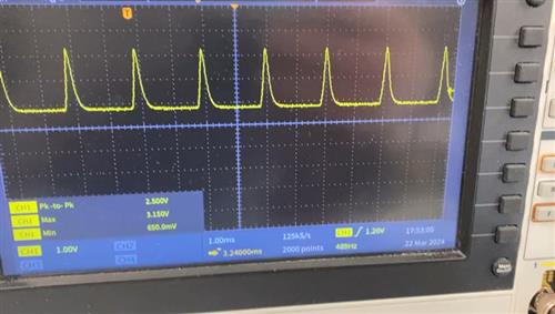
After rectifying the soldering issues, the digital potentiometer now responds to the control script. However, I've observed an unexpected behavior in the resistance value changes: rather than increasing linearly as my script dictates, the values exhibit some oscillations. This leads me to suspect that the data bits sent to the potentiometer might be inverted or otherwise not in the expected order. Here's an oscilloscope capture of the output wave that illustrates the issue:

Output Wave

Given this new finding, my next step is to investigate the bit order in my script and attempt adjustments to see if this resolves the oscillation in resistance values. I'll update with any progress or solutions I find.

Again, thank you all for your support.Output wave

\$\endgroup\$
1
  • \$\begingroup\$ i found out that the MAX5495 cannot be used as a resistor but just a voltage divider, so that's probably why i got that oscillation, i should have gotten the MAX5496 OR 97 \$\endgroup\$ Commented Apr 10 at 13:39

Your Answer

By clicking “Post Your Answer”, you agree to our terms of service and acknowledge you have read our privacy policy.

Not the answer you're looking for? Browse other questions tagged or ask your own question.