Your 100 MHz preamp is a common emitter amp stage. It's not popular, because the capacitive feedback from the collector to the base knocks the gain down even at 100 MHz except in case it's compensated by adding inductance or some other neutralization method. But then one would easily have an oscillator. Proper design based on inductors is tricky at 100 MHz and the amp needs tuning. A common base rf preamp in front of the mixer was and still is the standard workaround in FM radios built of discrete transistors. There collector-base capacitance is not a feedback route. See some old FM transistor radio designs to get the idea. Another non-inductor based workaround is "cascode amplifier", which will be seen later. Gilbert cell mixer uses it.
Resistors R18 and R20 can both even alone kill the signal so completely that the rf preamp and any input signals are useless even in case the preamp and the mixer were functional.
Gilbert cell is a way to build a double balanced mixer into integrated circuits. The basic idea was published at the same time also by others. Gilbert developed advanced versions, but the elementary version that you seem to reach is also called today Gilbert cell.
Your "Gilbert cell mixer" does nothing useful because its rf input is fed in a totally wrong way. R17 without DC blocking is another fatal error. In addition the mixer needs balanced load for full performance. These are all already said in the comments.
To understand the Gilbert cell properly for rf applications one should at first understand exactly a couple of simpler circuits

simulate this circuit – Schematic created using CircuitLab
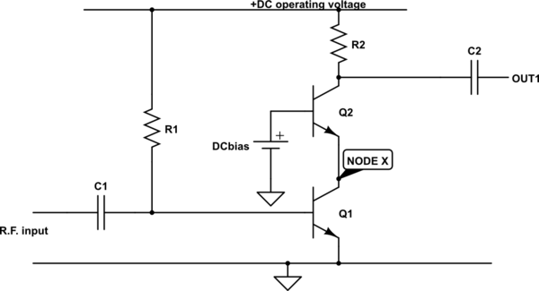
In the image above transistor Q1 works as a common emitter amplifying stage. The collector doesn't have directly the usual resistor to +DC and the output via a capacitor. There's another transistor which forces the voltage at NODE X to stay at value DCbias - 0.7 volts. It's constant as long as DCbias voltage is constant.
The extra transistor makes this "cascode amplifier". The current through R2 is what Q1 draws depending on the idle current based on R1 and the momentary R.F. input voltage. The amplified output voltage is available from OUT1.
The cascode configuration removes all AC voltage from NODE X. That removes the capacitive feedback inside Q1 through the BC junction capacitance which could turn down the available RF gain or cause operation as oscillator when there's inductive circuits in the base. Cascode amp is a way to construct wide band rf amplifiers without critical circuits needed to neutralize the effect of the capacitive c to b feedback inside the transistor.
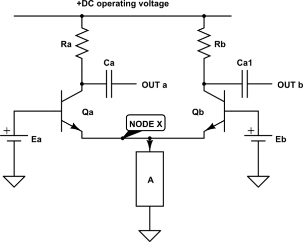
The other "must to be known" elementary circuit is the long-tailed pair; it's 2 transistors emitters connected together. The idea how to use it in signal switching is shown below:

simulate this circuit
The long-tailed pair is the basis of voltage comparators. Transistors Qa and Qb both try to keep the voltage at NODE X in a certain value; Qa aims voltage Ea-0.7V and Qb aims Eb-0.7V. The higher value wins. If Ea > Eb transistor Qb is blocked out by too low BE voltage. Anything the common emitter load A bothers to draw at voltage Ea-0.7V goes through Ra. If Eb > Ea all current A draws goes through Rb.
In your case there's 2 long-tailed pair signal switches. Emitter load A is for the first one transistor Q6 and for the second one transistor Q7. Both of them work as the lower half of a cascode amp. The upper half is that part of a long tailed pair which happen to be in the game depending on the voltage on the base. The possible AC output voltage is available at OUTa or OUTb depending which of Qa and Qb is not blocked.
If voltages Ea and Eb are close each other, say closer than 50 millivolts there's a transition zone where both transistors are operating. That gives possibilities to construct linearly operating multipliers instead of hard switching. But it's not used in rf mixer applications.
In your circuit amplifiers Q6 and Q7 should get the RF input in opposite (=180 degrees shifted) phases. That doesn't happen. It could happen if you connected both ends of the rf transformer secondary to the bases of Q6 and Q7 (without forgetting the obligatory idle base current DC path).
Your long-tailed pairs should both get the output of the LO to the bases as summed to idle DC bias voltages, but the LO output is needed the phase reversed for half of the l-t pair transistors. The idea is to switch the amplified rf signals from Q6 and Q7 to the balanced output lines directly or as phase reversed depending of the momentary polarity of the LO output signal.
LO doesn't need balanced output. In theory it could well do the needed switching if half of the long-tailed pair base voltages are simply kept as constant DC values and that's what you have already done. But the transformer secondary L15 should be connected between the bases of Q6 and Q7. The same DC component would be ok for both bases.
Load R17 should have DC blocking capacitor in series and to get the benefits of the balancing it should be connected between the outputs of the long tailed pairs. In radio receivers the load is the intermediate frequency filter. Constructing it properly so that neither of the filter inputs is the ground is simple if you have a transformer in the input of the filter.
As already said in the comments: Try at first the mixer, add the rf preamp after you have seen the mixer works. Do not add the rf preamp before you have seen that it works alone. I'm afraid it's an oscillator. Without intermediate frequency filtering at the output of the mixer you do not get a clean output, it contains also the sum frequency mixing result, mixing results with LO output harmonics + possible spurious outputs caused by distorting the input signal.
FFT spectrum analysis is useful in visualizing the mixing results and how effective is the I.F. filtering. But spectrum analysis is a new swamp if one doesn't understand its math basics and the requirements for valid results.


