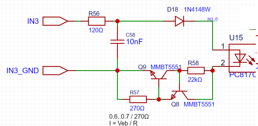
I'm designing relatively wide voltage range (3..24V) isolated input for reading the push-pull output state. Input source is going to be from a water counter, some 3-phase motor controllers, water level sensors so I'm assuming long wires, some interferences from a starting motors etc.
Currently I ended up with a constant current source scheme from this answer (avoided TLV431 because of unavailability at the location of board assembly, dont need hight precision either). For the input part the following additions were made:
- D18 is to shift the lower bound
- R56+C58 to filter higher frequencies and limit transient/ESD/surge current
- Going to add TVS (unidir, 24V standoff) in parallel to C58
Scheme is tuned to draw ~2mA from the signal source. RC filter set to 130 kHz because a PWM input might be applied.
I have two questions here:
- does TVS protect a current limiting circuit? Simulation in proteus shows that it should work as expected, however cant simulate ESD spikes
- does opto-coupler's fall/rise times of ~4..18uS means than I can safely decrease RC cutoff to ~27 kHz?

