0
\$\begingroup\$

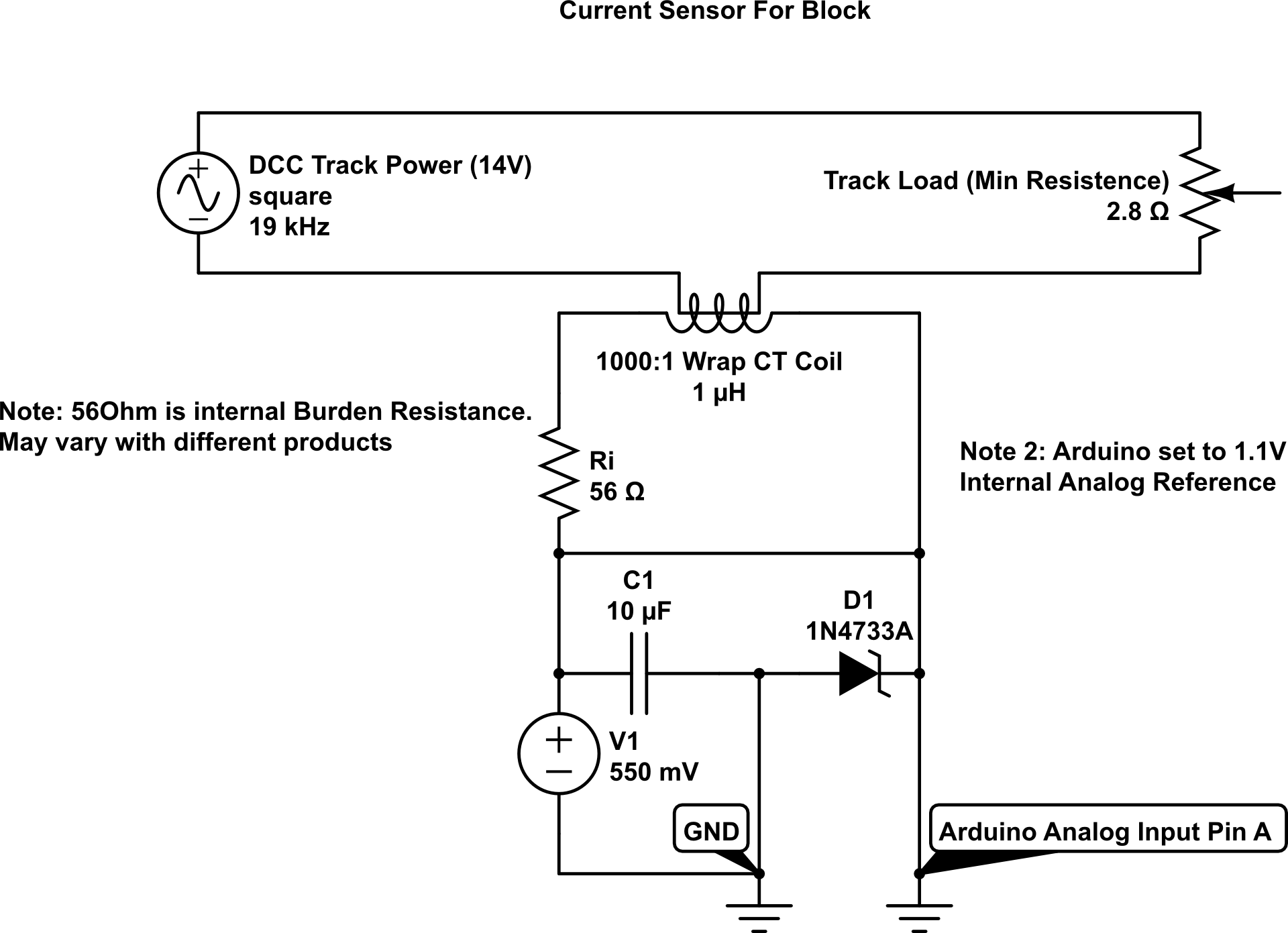
Question: Is this safe, or is there a better way to do it? Is there a ready made solution that can also handle shorts to protect Arduino?

The problem: It's primary is square wave AC. And it can go from 0 amps to a short circuit conditions (5 A max typical - 50 mA on secondary CT coil, auto shutoff in ≤ 0.1 s). A short condition would cause a large voltage spike on the analog input using a CT coil.

I thought a 5.1 V Zener could protect the Arduino input from OVER voltage and negative voltage. But I told this was problematic from other post.

Background: I'm trying to measure ultra low currents using a 1000:1 ratio CT coil with an internal resistance of ~56 ohm. (Example 1 mA on the primary would be ideal but 10 mA would be acceptable.) If necessary, I can increase the sensitivity with more wraps on primary, or using another burden resistor in series.

My idea was to use 1.1 V internal voltage ref. That gives me about .001 V / step. But as this is AC, I need an offset voltage of 550 mV (0.55 V).

I don't care about larger currents, just that there is a smaller current indicating load on the primary.

Adding diodes, or load across the primary isn't an option as it will either alter voltage output, or generate a ton of wasted energy @ 5 amps (low ohm shunt).

Here's a diagram of the circuit in question:

Current Measurement Circuit Diagram

\$\endgroup\$
2
  • 1
    \$\begingroup\$ You've shown the burden resistor in the wrong place and you haven't linked to where you were advised about the zener diode (likely someone who doesn't know about zeners). \$\endgroup\$
    – Andy aka
    Commented Apr 25 at 16:56
  • \$\begingroup\$ The burden for the CT coil is Ri in the diagram. As I said, it measures ~57Ohms across the coil. The zener has leakage currents which mess up the AD converter. \$\endgroup\$ Commented Apr 25 at 17:58

1 Answer 1

0
\$\begingroup\$

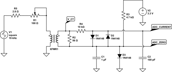
You placed the burden resistor, here R2, in series with the coil, but it must be parallel to it.

This circuit creates the 550 mV ADC center voltage via R3 and D3. This varies with temperature, but if you read ADC_ZERO with one ADC channel and ADC_CURRENT with another channel, the difference will be nearly as precise as the internal Arduino ADC reference.

D1 and D2 clamp the voltage from the transformer to +/- 550 mV relative to the center voltage with a soft characteristic.

Have a look at the time domain simulation to see the clamping at high currents.

The transformer in this circuit may behave different form yours, it is just guesswork.

schematic

simulate this circuit – Schematic created using CircuitLab

\$\endgroup\$
1
  • \$\begingroup\$ Thank you so much. Luckily I have all the parts. I'll give this a test this week. \$\endgroup\$ Commented Apr 27 at 20:02

Your Answer

By clicking “Post Your Answer”, you agree to our terms of service and acknowledge you have read our privacy policy.

Not the answer you're looking for? Browse other questions tagged or ask your own question.