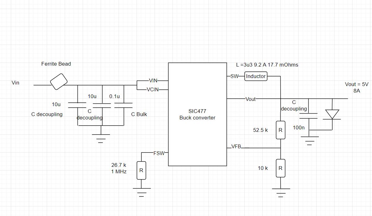
Checking the datasheet, page 10 "Output Capacitor Selection". I'm using Python as a calculator, and putting it in as code, for easier copy paste:
Vin=16.8
Vout=5
L=3.3e-6
duty=Vout/Vin
F=1e6
Ton=duty/F
Toff=(1-duty)/F

(Vin-Vout)*Ton/L
1.0642135642135642

Iripple=Vout*Toff/L
Iripple
1.0642135642135642

Iout=5
Minimum Cout according to the "Transient response" condition (equation 2) for 50mV overshoot:
L*(Iout+0.5*Iripple)**2/(5.05**2-5**2)
0.0002009828417522101
So, 200µF. Now how much ripple would we get with 20µF?
Iripple*(1/(8*20e-6*1e6)+0.002)
0.008779761904761905
So, 8mV. And with 100nF:
Iripple*(1/(8*100e-9*1e6)+0.05)
1.3834776334776335
You get twice that, but well, it won't work with 100nF obviously anyway. Ripple voltage is inverse proportional to Cout, so you need a lot more µF.
If you don't care about transient response, you can use something like 20µF. If you do, use 200µF or more.
This should be a low ESR cap, I'd recommend a few 10µF 16V X7R 0805 MLCCs in parallel for low inductance, I see you used 10µF MLCC on the input, so hopefully you have some left and don't need to order 10 cents of parts plus shipping!
For good transient reeponse, a 220-470µF low ESR polymer cap should be used in parallel, for example. I really recommend it, if you don't want to have large voltage overshoot when the load turns off. Or maybe all ceramics, but in this case, MLCC capacitance loss with bias should be taken into account.
According to the datasheet, "The device is internally compensated and
is stable with any capacitor. No external ESR network is
required for loop stability purpose" so it should be easy.

