15
\$\begingroup\$

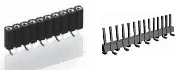
I want to join two PCB boards with "Headers" type connectors, like this image:

enter image description here

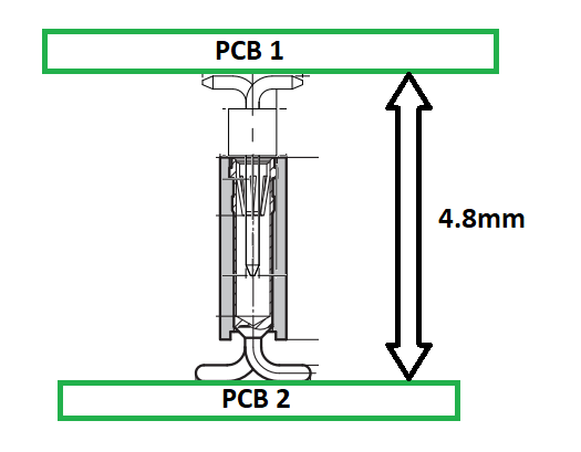
But the separation between both PCBs must be 4.8mm, as shown in this other image.

enter image description here

But with the connectors mentioned, they are very long and I cannot find a separation, nor close to the desired value.

I have seen some special connectors (SMD/SMT), but I can't find them.

Any suggestion or comment is welcome.

\$\endgroup\$
4
  • 3
    \$\begingroup\$ In the past I’ve used samtec.com for their online catalog and free samples. They have a decent selection of standard (I.e. free sample) variant lengths. \$\endgroup\$
    – MarkU
    Commented Jun 25 at 21:10
  • 1
    \$\begingroup\$ How much space do you have on the other side of the board? Through-hole sockets are an option here. \$\endgroup\$
    – vir
    Commented Jun 25 at 21:13
  • \$\begingroup\$ @vir Thanks for write. Only a PCB could have through holes. The others is a touch type PCB and there is no separation between the plastic sheet of the box that contains it. \$\endgroup\$ Commented Jun 25 at 21:17
  • 1
    \$\begingroup\$ Similar question: electronics.stackexchange.com/questions/666093/… \$\endgroup\$
    – user85471
    Commented Jun 25 at 22:00

5 Answers 5

26
\$\begingroup\$

The shroudless strips you plan to use are fragile and tend to rip SMD pads off the PCB. I strongly recommend you use mezzanine board-to-board connectors instead.

My Identiconn utility lets you select the mating height of mezzanine connectors. For 4.8 mm mating height, it lists 17 parts.

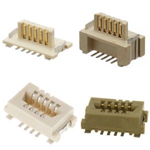
Of those, I would recommend the Amphenol Conan MezzSelect because it's small and it is compliant with variations in the board spacing, giving you more flexibility.

Amphenol Conan MezzSelect

{Source: Digikey}

\$\endgroup\$
15
\$\begingroup\$

Using standard header pins/sockets mounted on their side, you can get this down to <3mm.

Two PCBs

\$\endgroup\$
4
  • 2
    \$\begingroup\$ That's a good idea. And economical, since the other options are not cheap connectors \$\endgroup\$ Commented Jun 25 at 22:23
  • 6
    \$\begingroup\$ Hard to do with automated assembly, or accurately by hand, though. An alignment jig might be handy (not sure how one could do that with reflow..). (And yes, there are right-angle SMT headers, but placement shifts some during soldering, and machine placement isn't always exact to begin with.) \$\endgroup\$ Commented Jun 25 at 22:37
  • \$\begingroup\$ Yes, that's the bad side of that solution, getting it in a precise position seems a little difficult. \$\endgroup\$ Commented Jun 25 at 22:59
  • \$\begingroup\$ I gather there are SMD versions and through hole/right angle versions of these parts that are designed to be mounted in this fashion. The SMD parts have their leads kinked in such a way that the leads lie flat against the PCB, which would help with assembly, while the through hole/ right angle versions would be located better by their pins. What I've done here was use what I had on hand. \$\endgroup\$
    – user85471
    Commented Jun 27 at 21:44
13
\$\begingroup\$

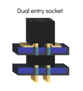
You can use pin headers if you select a "pass through" or "bottom entry" types:

The idea is illustrated here (Source):

enter image description here

Placing them on opposite sides, you can get the PCBs flat against each other.

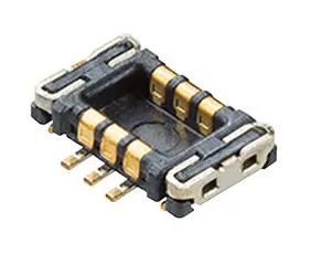
Or low profile mezzanine connectors (Source):

enter image description here

\$\endgroup\$
6
\$\begingroup\$

Headers do two things: provide an array of electrical connections, and mechanical alignment. Depending on how many pins, and how many are arranged on the board(s) and where, rotational alignment may be weaker, but location is always dictated by the pin and socket.

Strength is determined by header type and mounting; SMT headers like shown, you don't want much stress on, as the solder joints, or pads themselves (foil-laminate bond), aren't especially strong. SMT connectors are best for low stress, low cycling connectors (e.g. internal, user-inaccessible), and providing vibration damping and strain relief is recommended.

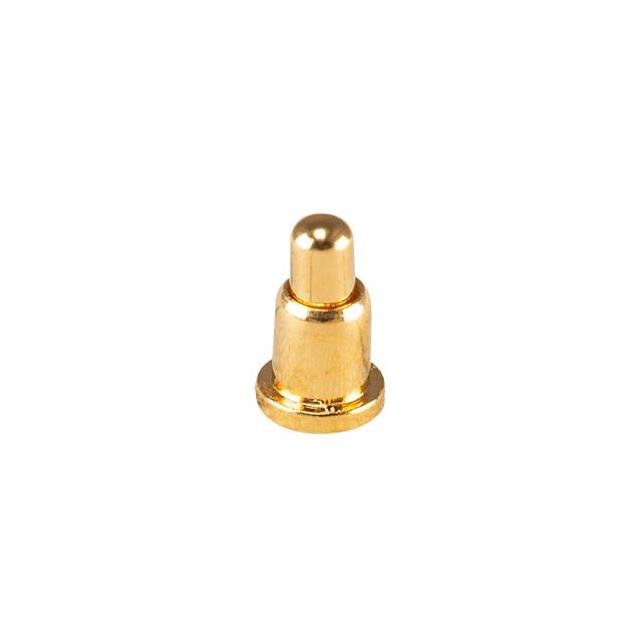
You might consider separating these functions, by using a spring or pogo-pin header, and separate mechanical alignment. The electrical contacts can then be simplified, perhaps permitting a lower profile.

Headers without alignment include spring contact arrays like TE Connectivity AMP Connectors 2199055-2, KYOCERA AVX 009188006020062, or battery connectors like KYOCERA AVX 009155005002016; pogo headers like Preci-Dip 811 (or Mill-Max), and targets like Preci-Dip 800, Mill-Max 319, etc., or plain PCB pads (preferably hard gold plating; ENIG has very little cycle life, let alone against vibration).

There are also single pogo pins and targets such as here: Contacts, Spring Loaded (Pogo Pins), and Pressure | DigiKey; effectively, you might craft your own bespoke connector by arranging pins in ideal locations, rather than having to collect them into headers.

Locating pins and mounting screws/standoffs transmit between-PCB stress and vibration, addressing one of the drawbacks of using headers alone. (See also: board edge guides to maintain orientation, especially for right-angle mounting with headers, edge connectors, in card cages, etc.)

Alignment pins can be a part of the enclosure, sliding or press fit into a PCB (any standard mechanical parts apply: hard pins, roll pins, etc.), or press-in or swaged hardware. For the latter, see PEM locating pins for example. You may find press-in or solder nuts, studs, standoffs, etc. useful for various mechanical assemblies. Examples: Keystone 24939, Würth Elektronik 9774030360R, PEM SMT types, etc.

\$\endgroup\$
1
  • \$\begingroup\$ Woops I wrote my answer mentioning pogo pins without realising you had it in there. My bad. \$\endgroup\$ Commented Jul 17 at 22:44
0
\$\begingroup\$

Are you set on connectors? You could use pogo-pins on one board and plain copper pads on the other, and bolt the boards together so that all pins make contact with the pads. The pogo pins are spring loaded.

enter image description here

Aside from that, first thing I thought was "does he need it to be disassemble-able?" because the simplest would simply be to use a regular header and solder it on the other board (for 2.54mm spacing) or use a custom spacer when bolting the boards down (for higher, up to the contact length and some). But I'm sure you already thought about it long ago, so it's more like a note.

\$\endgroup\$

Your Answer

By clicking “Post Your Answer”, you agree to our terms of service and acknowledge you have read our privacy policy.

Not the answer you're looking for? Browse other questions tagged or ask your own question.