2
\$\begingroup\$

I have a version of an 870MHz RF front-end based on the CC1190 PA/LNA based on an existing design that was ported to another PCB, manufactured and assembled for eventual use in a prototype. We'll call this revision A. The boards for rev A were manufactured and assembled, and eventually retrieved and tested for correct functionality and possible bugs etc. The hardware bugs on the board were tracked down and eventually another PCB revision was made, we'll call this rev B.

The B boards came back from manufacture and further testing was done to track down other potential problems etc. One problem that remains unexplained is the measured impedance mismatch on the front-end input, on the SMA connector. The VNA measured SWR / S11 between the revision A and revision B boards is significant, even though no major modifications were made to the routing, and certainly no changes to schematic / BOM values were made as they were not the target of debuging. This is because this part of the circuit was carried over from another already working circuit, so there was “no need to fix something that wasn't broken”.

Alas, now there IS something broken on this part of the revision B of the PCB that was not initially the case on revision A ?!? Between A and B, I am looking at an SWR difference of 2 and 5,9 respectively and an input impedance of 43-j41 Ω for A vs 9-j12 Ω, 12.2-j14.5 Ω and 11.7-j12.8 Ω for 3 boards of B at 870MHz. This was measured with a VNA calibrated to the input SMA connector reference plane, with the LNA of the front-end activated as if it were receiving. Between the SMA connector and the RF front-end there is less than 2cm of microstrip, including pasive 0402 components etc. This impedance was measured due to the prior observation, on about 8 boards of revision B, of a lower output power than usual, and a lower LNA gain in reception. I have not measured the SWR of all 8 PCBs but I am assuming there will be similar impedance mismatches to cause the lower output powers (about 3dB less than expected). Now, an SWR of 2 is reasonable if not the best, but SWR of 5,9 is bad ! This is confirmed by the 9-j12 Ω which is way off the 50 Ω target the front-end was designed for.

As I mentioned, this part of the circuit on the PCB was not one that required any modifications, but of course there were some minor shoving around of ground vias to make room, and/or routings underneath the RF ground plane but mostly > 95% of the routing of the RF front-end part was untouched between revisions A and B, including absolutely no changes to the RF circuit components, values or tolerances etc.

I have considered the following possible reasons with some more likely that others, and some more difficult then others to prove or discount :

  1. Possible bad component placement at the assembly house ?!?! I have thought about this but the manufacturer is adamant it was not possible and it would not have occurred. Any suggestions here ? Or remarks of such things occurring from personal experience ? Quick ways to dispel this ?
  2. Possible damage to RF front-end during assembly ?!? Again the manufacturer is adamant it could not be possible, and it would be strange this happening on all 8 boards, but nevertheless a potential source of the problem to consider. (NOTE I have replaced the front-end on one board and there seemed to be an improvement but cannot confirm 100% as the component was heated for rework).
  3. Most recent modifications to the routing could have impacted enough on the new boards ?!? As mentioned, only about < 5% of vias and or power-tracks would have been slightly displaced or in some cases the ground-plane through-vias were turned into micro-vias between component and RF ground plane to allow for more routing space underneath the RF ground plane. I would be very surprised if this may have changed the SWR from about 2 to about 6 like that ! Nevertheless something to consider just to be fair to everybody.
  4. I've heard a suggestion that a lower substrate thickness could increase the parasitic capacitance on the 0402 components pads and maybe take the match "out of wack". It is true, the previous design from where this front-end was sourced, had less overall layers and there may have been a substrate separation to the RF ground of about 0.2mm or at worst say 0.1mm for a 1mm total size board. The new FR-4 PCB layer stack-up is different in that there are more layers and the PCB is now a standard 1,6mm with an 0,08mm RF to Ground plane substrate separation. After some quick estimations for the 0402 pads, the expected parasitic capacitances to the ground plane come to about < 0,16pF per pad, and on the front-end LNA input pins the parasitics come to about < 0,3pF per pad. I'd find this hard to believe it could become such a problem though at 870MHz, given that some of the capacitances have tolerances of +/- 0.1pF, so adding another 0,16pF in || to a 12pF or even a 3,3pF just doesn't seem to convince me ... Nevertheless something to consider.

So here are some possible causes considered that could see this vast change in SWR from one revision to another, but I'm sure they may not be the only ones. Any other suggestions would be extremely helpful and welcomed.

Any suggestions as to why one might see such a variation in SWR from one revision to another, knowing that the original design was made for 50 Ω nominal impedance, and on several initial boards (such as revision A) this was measured to be close enough to 50, but not on revision B ??

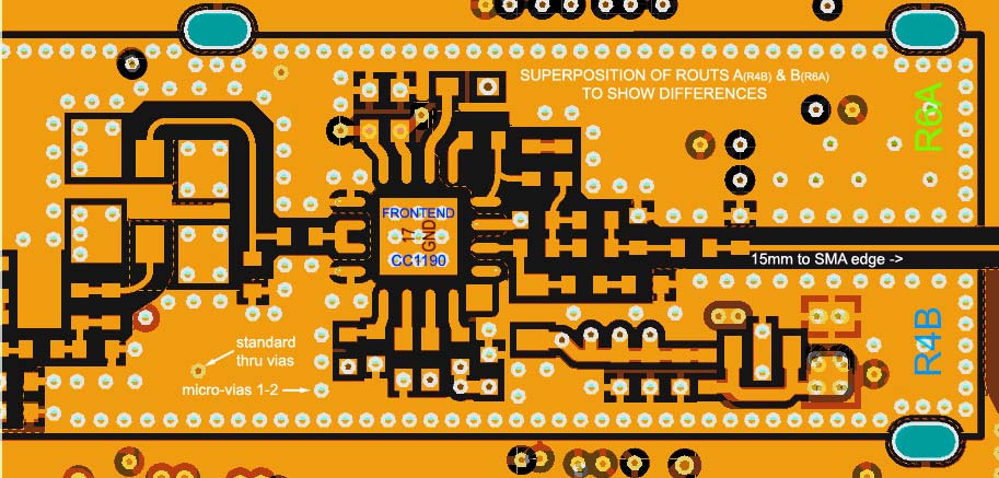
Below is a superposition of the two routs A & B of the front-end, showing minor differences (where dissimilar colourations). Ground-plane vias are micros 1-2. Superposition of routs A & B
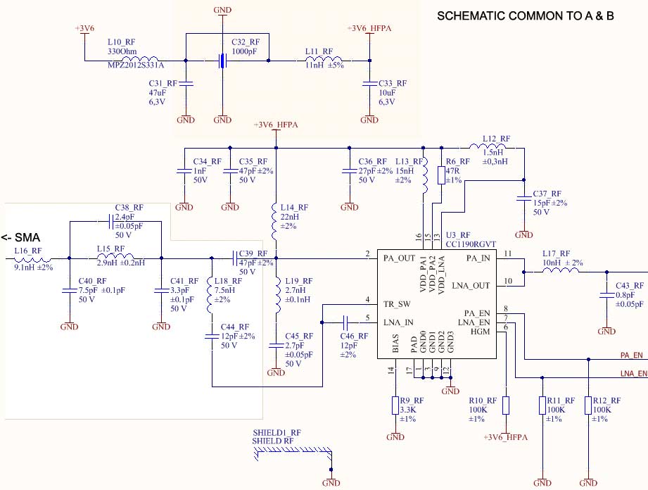
Below is the schematic common to both routings A & B. enter image description here
And what follows is the side-by-side layouts of the top layer for A & B. Bottom layer is shown for version B as version A just had the large cap next to the ferrite. Otherwise there are no components on the back.

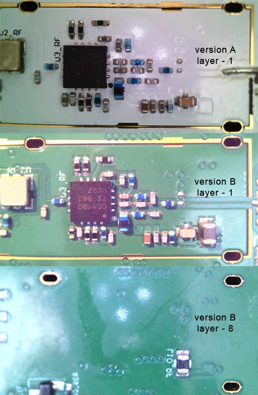
enter image description here

\$\endgroup\$
11
  • \$\begingroup\$ Is it the same board manufacturer? Did you pay for controlled impedance? \$\endgroup\$
    – Justin
    Commented Nov 4, 2020 at 14:27
  • \$\begingroup\$ Schematics, boards layouts, photos? Exactly what 'improvement' did you get on the reworked board? \$\endgroup\$ Commented Nov 4, 2020 at 14:39
  • \$\begingroup\$ @Justin - Impedance control: Yes ! And it was from the same PCB manufacturer. \$\endgroup\$
    – citizen
    Commented Nov 4, 2020 at 14:45
  • \$\begingroup\$ @BruceAbbott - The improvement is going to SWR=4.1 with the impedance being still around 13-j13 Ohms, so somewhat but not a definitive ... \$\endgroup\$
    – citizen
    Commented Nov 4, 2020 at 16:40
  • \$\begingroup\$ Your 'superposition' is really hard to decipher. Can you show us photos of the two boards? Can you sweep the VNA across the band, and if so what differences do you see? \$\endgroup\$ Commented Nov 4, 2020 at 18:33

2 Answers 2

2
\$\begingroup\$

If this may interest you, after further elimination of all other possible causes, I got stuck into the output connector on some bare boards to reproduce a similar difference, but this time with simply a 50 Ohms 0402 resistor as the first shunt element to act as a load at the end of the micro-strip line. This also gave vastly different results, above 10% anyway.

After some calculations and simulations I realized the 1.3mm wide solder pad for the SMA edge connector was adding a 10 ohm section of transmission line to the otherwise 50 ohms line.

This in combination with the other parts of the circuit resulted in a significant alteration of the total impedance from connector to the amplifier resulting in a bad SWR, return-loss etc.

I fixed it by replacing the SMA with a smaller footprint connector which was an option on the board but not originally installed. So, yes the other previous board had an SMA edge solder on directly on the fine microstrip line that had its solder mask removed, so there was no SMA pad to introduce this extra low impedance line in series.

\$\endgroup\$
5
  • \$\begingroup\$ so just an extra wide solder pad caused SWR losses? wow. \$\endgroup\$
    – niko20
    Commented Jan 5, 2021 at 15:28
  • \$\begingroup\$ Essentially yes ! The passive components in the photos are followed by a 50 Ohm microstrip, then to an edge-mount SMA with a pad about 40% the length of the visible microstrip, then followed by about 180mm of 50 Ohm coaxial going to an antenna. This SMA pad has about 10 Ohms of impedance based on the substrate thickness, and this lowered the effective overall impedance in an unwanted way... The problem is that from a birdseye view loking at the board all seems tiny and it was unimaginable that the pad could cause this, but simulations confirm it ... \$\endgroup\$
    – citizen
    Commented Jan 6, 2021 at 8:31
  • \$\begingroup\$ Version A of the board was a version with a microstrip going all the way to the edge of the board that wasn't terminated with the edge-monunt SMA. It was actually the version that led to an additional SMA after ditching the U.FL. So the microstrip track had the original 50 Ohm width. In this version the soldermask was scraped off and an SMA was soldered on directly onto the microstrip, without the SMA pad as this was added in the subsequent revision B. The difference between the two boards was visible by measuring SWR and this was bad for the revised board ... \$\endgroup\$
    – citizen
    Commented Jan 6, 2021 at 8:36
  • \$\begingroup\$ Generally speaking, as one commented already, moving from an existing design, to another board, would normally assume no change in the routing of the design. This was unfortunately not possible, so the routing and stack-up was modified to some extent to accomodate the space constraints. \$\endgroup\$
    – citizen
    Commented Jan 6, 2021 at 8:40
  • \$\begingroup\$ Even though chip manufacturers mean well when they provide reference designs for applications to demonstrate their chipsets etc, often it is not practical to follow a design to the letter. In this case the reference was a 4-layer board with a stack-up suitable for a 1,6mm PCB. Our board had to be 10 layers with 1,6mm thick PCB.... As you can see this would not be "translatable" going from 4 layers to 10 layers etc. was not physically possible and the manufacturers would not accomodate this, ever ... \$\endgroup\$
    – citizen
    Commented Jan 6, 2021 at 8:44
1
\$\begingroup\$
  1. Possible bad component placement at the assembly house... the manufacturer is adamant it was not possible

Don't trust them. Bad component placement could have a dramatic effect, so it's the first thing you should check. You should test all the capacitors and inductors in the antenna circuit. For a quick test of the inductors, measure their DC resistance. It should be the same on both boards. Capacitors will probably have to be removed for testing. You could also try removing the parts from a good board and transferring them to a bad board (and vice versa).

  1. Possible damage to RF front-end during assembly ?!? Again the manufacturer is adamant it could not be possible, and it would be strange this happening on all 8 boards

I think it is highly unlikely for IC damage to cause the same impedance change on all 8 boards. In the comments you say you replaced one IC and the impedance was still not corrected, which is further evidence that the IC is not the problem.

  1. Most recent modifications to the routing could have impacted enough on the new boards ?!?

Yes, it's possible. However, assuming vias are the same diameter etc., I don't see anything on your boards that would explain such a large impedance difference. On the B board a capacitor (C34?) has made the top ground plane narrower as it goes past the output, but I doubt this would have a large effect.

  1. I've heard a suggestion that a lower substrate thickness could increase the parasitic capacitance on the 0402 components pads and maybe take the match "out of wack".

It certainly would. It would also increase capacitance of the traces between the pads, and reduce inductance of the vias.

adding another 0,16pF in || to a 12pF or even a 3,3pF just doesn't seem to convince me...

...assuming your calculations are correct. But 0.16/3.3 is 5%, and if your copy of the original design is already out of tune then another few percent might make a significant difference. Changing the substrate thickness is not something I would do if simply copying an existing design.

One more thing you might want to consider is that the boards have different solder masks. Solder mask introduces dielectric loss, which can vary depending on thickness and formulation.

\$\endgroup\$
14
  • \$\begingroup\$ So thanks for your suggestions, they could be very helpful. So in reply to them see below : \$\endgroup\$
    – citizen
    Commented Nov 9, 2020 at 8:24
  • \$\begingroup\$ 1. Bad component placement was my first point of contention, and I did look into it in replacing the 0402 capacitors and inductors on the antenna side. I purchased a new set of passives and replaced the ones on the board, without much effect. In the sens that I did not get an impedance that looked more like 50 Ohms as I had on board A. So this part I could eliminate... \$\endgroup\$
    – citizen
    Commented Nov 9, 2020 at 8:28
  • \$\begingroup\$ 3. The routing difference was mainly on a 47uf capacitor on the 3,6V PA supply. This was moved from layer 8 to layer 1. Much other than that is minimal. However I am getting in contact with the PCB manufacturer to request assistance with possible errors to the stack up that may have been introduced between revisions, that we may not be aware of. The concern is that most PCB manufacturers choose at their discretion the core and the prepreg materials (unless we request a custom at a higher cost) and this was accepted at face value as there was no reason not to. With hindsight it may be worth it. \$\endgroup\$
    – citizen
    Commented Nov 9, 2020 at 8:33
  • \$\begingroup\$ Further to point 3 there is a slight issue regarding the ground pins routing on the CC1190 based on the advice from the Ti datasheet on this component. Their Gerber files show a solid ground pour on the top layer 1 pouring allover the CC1190 ground pins to the central die pad. Instead I took an approach that in-pad vias on these ground pins be connected to the ground plane on layer 2 directly. with hindsight it may have been wiser to follow the recommendations to the letter... I may consider this should I require another revision of the board. So far I have no means to confirm or dispel this. \$\endgroup\$
    – citizen
    Commented Nov 9, 2020 at 8:40
  • \$\begingroup\$ 4. So this calculation is based on the capacitance of a square plate to an infinite plate, so it doesn't take into account any fringing effect or capacitance to nearby pads etc. It wasn't meant to be, rather to have some appreciation of the order of magnitude ... I would assume at 2,4GHz or higher these would be significant and important, but not at 870MHz. Nevertheless I may look into it further ... as you are right for a 3.3pF it makes a difference. There is an 0,8pF on the input to the CC1190 from the SAW side for terminating the SAW filter, and there this would be significant ... \$\endgroup\$
    – citizen
    Commented Nov 9, 2020 at 8:46

Your Answer

By clicking “Post Your Answer”, you agree to our terms of service and acknowledge you have read our privacy policy.

Not the answer you're looking for? Browse other questions tagged or ask your own question.