1
\$\begingroup\$

I have a signal (on/off) at 0/~10V that will control the on/off of an IC.

I need to invert the logic to operate as I want.

I have a power supply from a battery that will be 40-80 V.

I was thinking of using a MOSFET for this purpose but I have never designed something like this so I wanted to ask here for more experienced opinions and maybe another approach.

What parameters should I look for in the datasheet in order to select the right MOSFET?

\$\endgroup\$
2
  • \$\begingroup\$ Welcome! Is that all you need to do? No MCUs, LED indication or similar? How fast do you need to switch the output? \$\endgroup\$
    – winny
    Commented Jul 3 at 10:12
  • \$\begingroup\$ Thank you @winny . Yes that's all. It's an analog system the will enable that chip (max5035). No need to be fast. milliseconds are fine! \$\endgroup\$ Commented Jul 3 at 10:25

2 Answers 2

0
\$\begingroup\$

It's an analog system the will enable that chip (max5035).

enter image description here

Image from the datasheet.

As you can see, the MAX5035 has an enable input (on/off) that you can use. Replace the switch with a MOSFET and you should be good to go.

What parameters should I look for in the datasheet in order to select the right MOSFET?
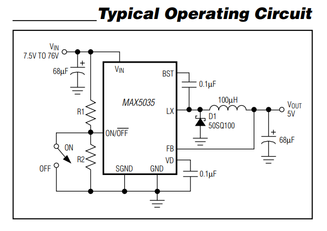
Choose a MOSFET that can withstand 100 volts drain to source. Or, decide on values for R1 and R2 (to set the under-voltage-lock-out value) and pick a MOSFET with correspondingly lower peak voltage withstand.

The drain current requirements will be in the milli amp region.

The data sheet gives example values for R1 and R2.

However, the data sheet also informs you that if you wanted to directly drive the on/off pin from a logic level (such as 3.3 volts or 5 volts) then you don't need to use a MOSFET.

\$\endgroup\$
4
  • \$\begingroup\$ Thank you Andy, I have this n-channel MOSFET link BSS138BK,215 and I am wondering how to do it exactly. As I read here link when I will apply 0V the "switch" will be off and if I have 10V it will be on. How will I invert this as I want? Should I go with P-channel? Sorry if this is too trivial but I am new to MOSFETs and try to decipher them! \$\endgroup\$ Commented Jul 3 at 15:03
  • \$\begingroup\$ @trelozakinthinos read my final paragraph; it tells you that don't need a MOSFET. So, now this question boils down to "how can I make an inverted version of a 10 volt logic waveform". Don't you agree? If you do agree, please explain what the current logic signal has to achieve when it is high i.e. when high, do you want the MAX5035 activated or deactivated? \$\endgroup\$
    – Andy aka
    Commented Jul 3 at 16:15
  • \$\begingroup\$ Andy you are right. My control signal is 0 or 10V. If it is 10V I want the MAX5035 to be off. And when control signal is 0V I want the MAX5035 to be on. That's why I need to invert it. Vin will always be 40-80V. I am replacing the TL2575HV-12IKTTR with MAX5030 which has inverted logic on the on/off pin. I hope that makes it clear now! \$\endgroup\$ Commented Jul 4 at 6:32
  • \$\begingroup\$ @trelozakinthinos if we are done here, please take note of this: What should I do when someone answers my question. If you are still confused about something then leave a comment to request further clarification. \$\endgroup\$
    – Andy aka
    Commented Jul 4 at 8:00
0
\$\begingroup\$

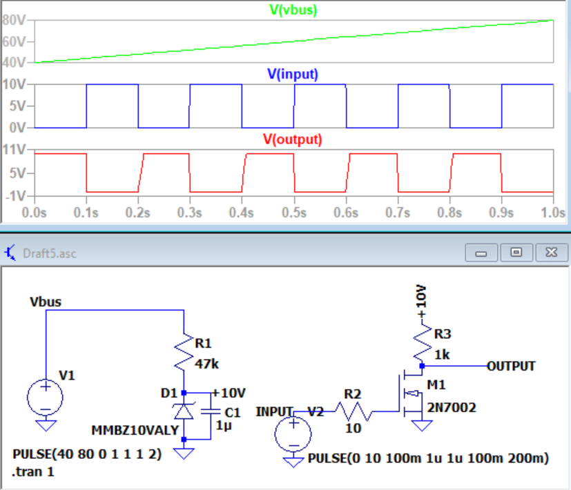
Many possible ways to make it happen. Here is one with only discrete components:

enter image description here

The downside is that it will consume a few mA of current as long as the battery is connected.

\$\endgroup\$

Your Answer

By clicking “Post Your Answer”, you agree to our terms of service and acknowledge you have read our privacy policy.

Not the answer you're looking for? Browse other questions tagged or ask your own question.