2
\$\begingroup\$

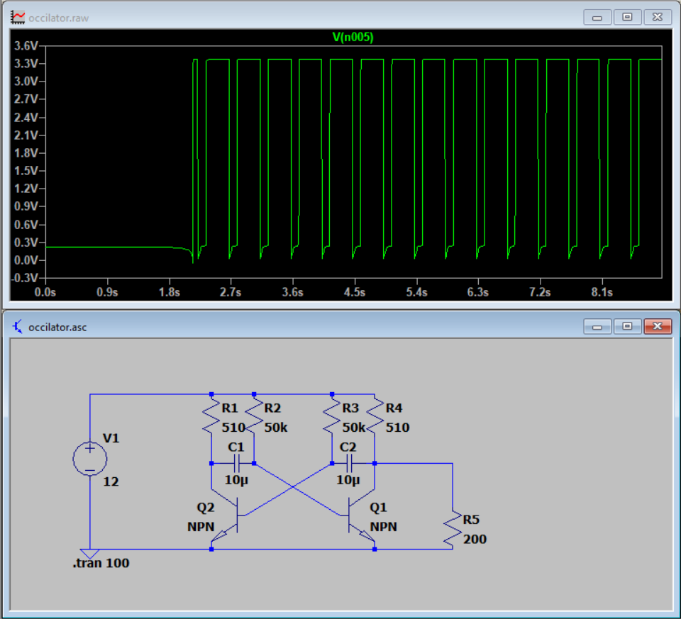
Square wave made by occilator, i dont know why its such a low output considering 12V input, probably the fact that it's in parallel

Yes hi so basically i'm wondering how to make the output oscillate between 0 and n volts, because in every one of these that i've made it never goes to 0 and that's a slight issue as im using it to feed into a linear mode mosfet where i need it to switch on and off instead of partially off. I don't know if there's some AC coupling thing that we can use here but i've never made that work with an astable multivibrator or if the resultant negative voltage would be good or bad for the mosfet turning on and off. Also ideally i need the oscillator to go between 0-10 volts where 10v is minimum high voltage in order to turn the mosfet fully on. Maybe i'm being too picky at this point but if anyone knows how to do all of that i thought it couln't hurt to ask

tldr: need voltage between 0-~12, dont know how to make 0V and assuming low voltage in chart is because of resistor.

\$\endgroup\$
10
  • 1
    \$\begingroup\$ Did you try with real transistor models? Try with 2N3904 instead of ideal NPN model. Also, avoid loading it with relatively small resistors. \$\endgroup\$ Commented Aug 7, 2023 at 11:09
  • \$\begingroup\$ I can definitely try reducing the load resistance and using real resistor models, maybe artificially introducing slight differences to create oscillation, but the thing is in real life the behaviour is much worse, but also kinda of better? 12v peaks but 2v minimums, ideally i just wanna shift it down 2 volts or even have 12v peaks and 0v dips. \$\endgroup\$ Commented Aug 7, 2023 at 11:09
  • \$\begingroup\$ @leasthollow What exactly do you want? Rail to rail operation? (0 V to 12 V?) Or what can you accept? \$\endgroup\$ Commented Aug 7, 2023 at 11:10
  • \$\begingroup\$ ideally yes, sorry for not making that clear, i didn't know the terminology. but yes thank you :) rail to rail is what I'm looking for \$\endgroup\$ Commented Aug 7, 2023 at 11:11
  • \$\begingroup\$ I simulated the circuit (without 200 ohms load) with real transistor models and I got this. It swings down to 100 mV above ground but it's basically the \$V_{CE-sat}\$ of the transistors. You may get lower by increasing 510 ohm resistances but that'll distort the pulses i.e. the rising edges will be "rounder". \$\endgroup\$ Commented Aug 7, 2023 at 11:16

4 Answers 4

6
\$\begingroup\$

It will never get to exactly zero as there is a voltage drop across the transistor, \$V_{CE_{(sat)}}\$ which can be several tenths of a volt with a bipolar transistor. A MOSFET might get you closer or you could use a negative bias to offset the output. You might also be able to put a diode in series to drop the output voltage a bit.

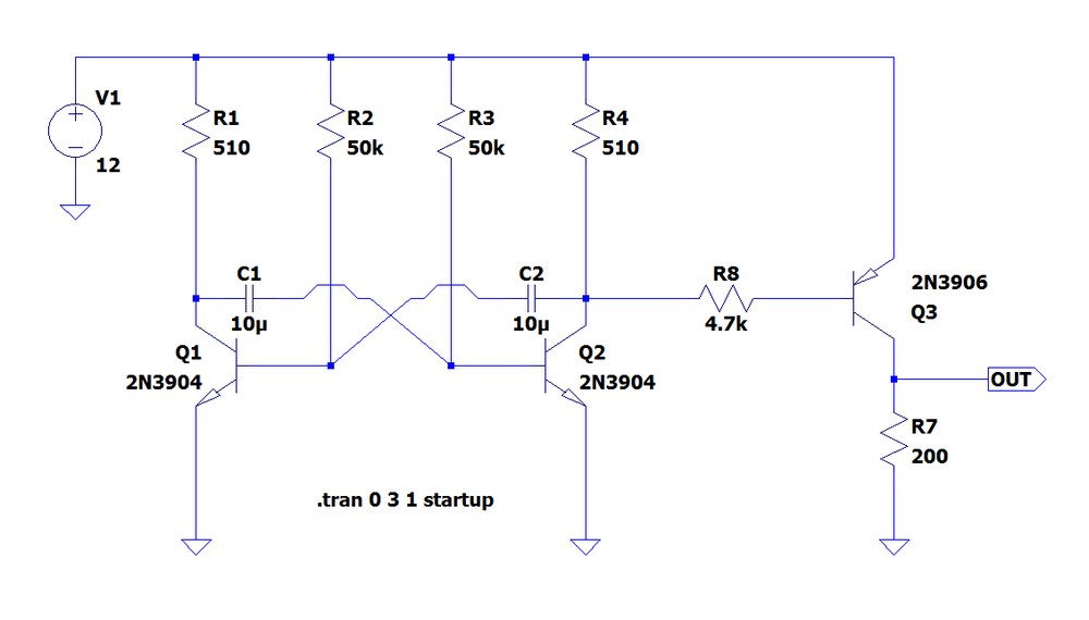
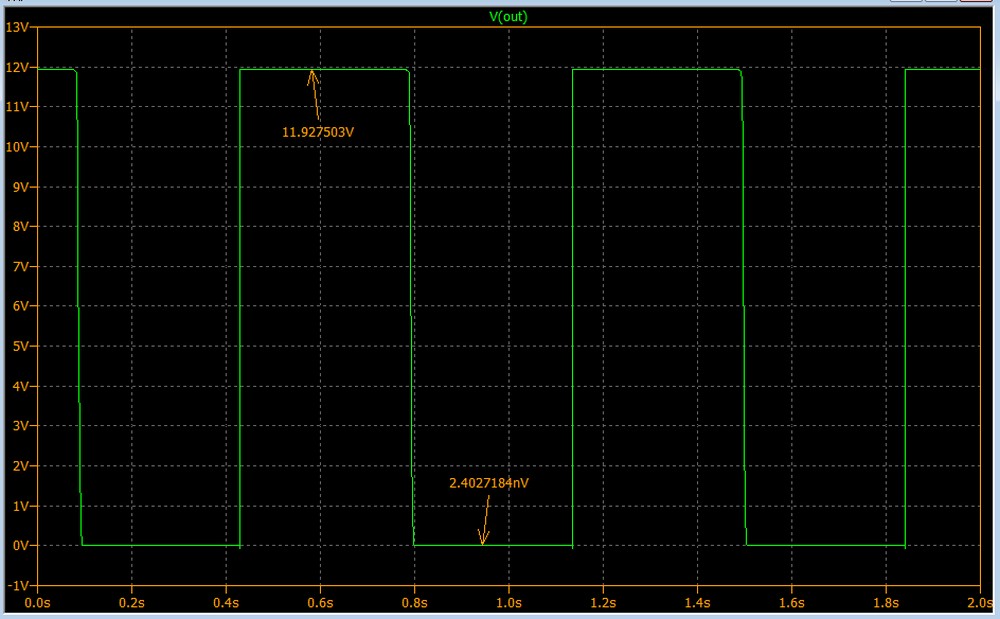
Another option is to add a PNP transistor, this places the \$V_{CE_{(sat)}}\$ drop at the top of the waveform instead of the bottom, so you'll lose a few millivolts on the high part but get much closer to zero on the low part.

Astable Multivibrator with PNP driver Astable Multivibrator with PNP driver waveforme

\$\endgroup\$
7
  • \$\begingroup\$ what do you mean use a negative bias (am slightly noob) \$\endgroup\$ Commented Aug 7, 2023 at 11:18
  • \$\begingroup\$ @leasthollow Self-bias is another approach to avoid a negative rail. Just FYI. But it has it's own details. You will probably need a 2-quadrant output driver added to this if you want rail to rail. There's a lot to understand and learn in making something akin to what I suspect you desire. It's not rocket science. But it's not trivial, either. And you will never get exactly down to zero volts without a negative rail. That's guaranteed. A few hundred millivolts within ground, yes. But not exactly zero. Not without a negative rail. Why not use a 555 or CMOS version of one? \$\endgroup\$ Commented Aug 7, 2023 at 11:26
  • \$\begingroup\$ is there anything particularly bad about a negative rail on a mosfet gate? and if not, how would you go about doing that, with the previously mentioned circuit? \$\endgroup\$ Commented Aug 7, 2023 at 11:33
  • \$\begingroup\$ well the main reason i was using an astable multivibrator is because i want to replace R2 with a potentiometer allowing me to change the duty cycle of the square wave easily. also because it's the only square wave generator i know and i wanted to make it work :| i guess i should be looking into other types of driver circuits \$\endgroup\$ Commented Aug 7, 2023 at 12:13
  • \$\begingroup\$ @leasthollow I mean you would put the oscillator common at a lower voltage than the ground for the rest of your circuit. If you look at transistor astable circuits in early computers you often see them have a positive supply and a negative supply. Also, see my updated answer, you might be able to get away with just adding a PNP buffer. \$\endgroup\$
    – GodJihyo
    Commented Aug 7, 2023 at 14:13
3
\$\begingroup\$

Turn it upside down, have PNP transistors. R5 should be removed. The result should be ok for driving the common N-channel mosfets at low (sub kHz) switching frequencies. At higher frequencies the dissipation during the state transition can become a problem. High enough transition speed needs special care in high frequency switching.

\$\endgroup\$
2
  • \$\begingroup\$ (I guess \$\text{R5}\$ is intended as \$\text{R}_\text{load }\$, lower value than collector resistor notwithstanding.) \$\endgroup\$
    – greybeard
    Commented Aug 7, 2023 at 11:44
  • \$\begingroup\$ That's possible. But it's a guess. The oscillation does not need it. And the application principle I suggested will not work with R5. The non-1:1 duty cycle can be achieved otherwise, for ex. by having different capacitors or base resistors. \$\endgroup\$
    – Ormand
    Commented Aug 7, 2023 at 11:59
2
\$\begingroup\$

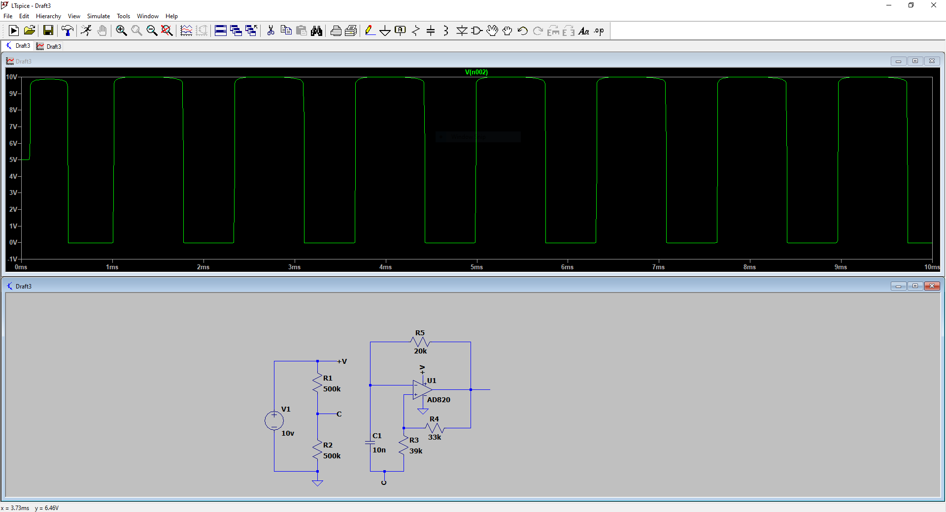
Personally, I see this as a great case for an Op-Amp-based Astable Multivibrator. Since you can buy rail-to-rail op-amps, you don't have to mess around with adjusting the output voltage with capacitors and diodes.

A point of advice, however, make sure you select the right IC for your application as Op-Amps have power, voltage, and switching speed limitations.

In the design below, you can adjust the frequency with by adjusting R5 or C1. (You can also do this with R3 and R4, but the values are chosen to eliminate a natural log when computing frequency)

Additionally, the output voltage range is based strictly on the input voltage source, just make sure your IC is rated for it.

enter image description here

Notes:

The R1,R2 voltage divider is to create the "virtual ground" 'C'. All this does is allow me to use GND as the negative rail with respect to 'C'. The voltage divider technique works, but it does affect the multivibrator, so I would use an active virtual ground to ensure isolation.

Here is a great article about op-amp-based multivibrators and all the math you'll need to know to tune them: Op-Amp Multivibrator

\$\endgroup\$
1
\$\begingroup\$

Increase R1 and R4 -- they only allow a forced beta of about 100 (R2/R1) for the NPNs and that isn't enough to allow them to saturate well.

You should be able to get < 100 mv at the low V output.

Try R1=R4=4.7k

\$\endgroup\$
1
  • \$\begingroup\$ A higher value of R1 and R4 does indeed lower the voltage in the "off" position, but does create a much slower rise time, i'll have to do some testing with different values and find out if that slow rise time is an issue. Thank you for your reply. \$\endgroup\$ Commented Aug 8, 2023 at 4:18

Your Answer

By clicking “Post Your Answer”, you agree to our terms of service and acknowledge you have read our privacy policy.

Not the answer you're looking for? Browse other questions tagged or ask your own question.