Well, without any detail of what device is in question, or applicable patents if any, there are two typical possibilities.
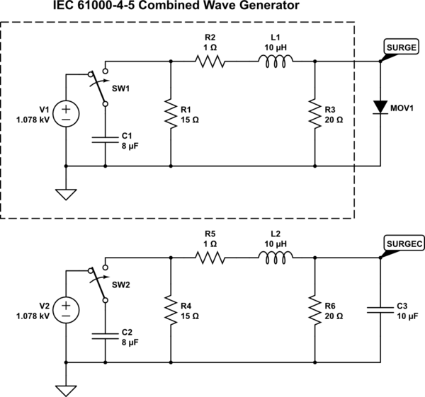
First, consider the equivalent circuit used to test surge:

simulate this circuit – Schematic created using CircuitLab
C1 roughly corresponds to the spare charge leftover from a lightning direct or induced strike. R1-R3 and L1 set the rise time, duration and discharge of the waveform, as well as the effective impedance of around 2Ω.
The mains distribution system uses SPDs (big stacks of MOVs, fused with an explosive bolt to rapidly separate the protector if it overheats or otherwise fails), which being up on poles, have significant stray inductance to ground; ground itself is also lifted by such a strike, and nearby loops (hence: induced lightning) pick up the EMP anyway, so the whole process is very "squishy" to analyze in the vicinity of an actual strike. At some distance, enough SPDs have been encountered that the peak voltage is within expected limits (maybe 3-5 times nominal line peak voltage), within the ratings of distribution transformers, and the output is simply a transformed-down surge. Or the low-voltage side experiences induced lightning directly, but in either case a few kV is a typical maximum limit for differential surge.
As there's some distance between the source (or last low-impedance point anyway, SPD or otherwise) and load, there is some inductance, which also sets the approximate impedance as this is a dynamic event. Thus we arrive at a circuit something like the above (it's called "combined" because it has a 8/20us response for current into a short circuit, and 1.2/50us response for voltage into an open circuit; both extremes of waveforms, and the intermediate cases, find use in EMC testing).
Note that let-through is not generally concerned about nanoseconds, but microseconds. ns's are fairly trivial to filter: such signals (100s MHz) "don't like to stay in wires", i.e. they are easily lost to radiation, dielectric absorption, mutual inductance, etc., so, say an arcing process on a pole some blocks away, doesn't transmit all that much to a given customer, at these frequencies. Granted, it might still be significant voltage as RF goes -- tens of volts perhaps, but just not full-amplitude surge voltage. After going through distribution cables, transformers and wiring, bandwidth is limited to some kHz, and maybe a strong surge still comes through in the low-µs time scale, and that's about it.
Mind, nearby strikes can do all sorts of nasty things, in terms of bandwidth or risetime as well as amplitude. But, that's very much getting into a different regime altogether, and demanding very high reliability (or any reliability on very unfortunate sites e.g. antenna/tower, skyscraper, mountain top, etc.) requires different solutions (yard grounding grid, facility shielding, more and bigger SPDs and filtering, etc.). So we tend to consider surge protection within the extents of commercial equipment and IEC and related standards.
ns scale let-through is also produced by discharge type SPDs, like GDTs (gas discharge tube) and spark gap structures. In this case, it takes some time for the gas to ionize and become conductive. I suppose a facility might be protected by such structures as a first-line defense, and then the ~ns scale overshoot would be easily found within the facility itself. In any case, it's very easy to filter frequencies this high (little capacitance or inductance is required), it's harder to shield it (again, because it "doesn't like to stay in wires", which means equipment near such (unfiltered) wiring can experience problems too).
Anyway, back to the circuit: MOV1 is a diode, crudely modified to give a MOV-like characteristic; CircuitLab doesn't have a MOV component and I can't paste in a SPICE model. If you run the simulation with MOV1 or C3 deleted, or replaced with a say 1mΩ resistor, you can see the above waveforms as claimed. As shown, we get waveforms such as:

Compared to the raw 1kV peak, both seem to have significant effect. 10uF obviously isn't very large in relation to the 8uF source, but we can make it much larger, 100uF say, without running into much problem at mains frequency.
And so we come to one possibility: just load it down with enough capacitance to quash the surge.
The other possibility is a more subtle approach: clamp the surge into a large capacitor, but use diodes to do it. This draws a small idle current from the line (costing some power that the plain shunt cap might not), but can keep the peak voltage quite low: maybe some 10s of V above nominal peak. The capacitor normally stays charged to nominal peak voltage, and gets charged up a couple volts more after an event. This doesn't really need to discharge back into the line (and also is supposed to skate over multiple cycles, so can't exactly return energy in sync at any given point anyway), so I suspect isn't what they're getting at here.
As for power dissipation, that's simple: a direct capacitor (and nothing else; their description would seem to be applicable to this, where the "return energy back to the load" circuit is a trivial wire link) always draws and returns some energy from the mains. When the draw and return are phased very accurately (close to 90°), the average loss is near zero. An ideal capacitance does this at exactly 90°; real capacitors have some ESR, which reduces the phase shift and dissipates power.
As for power or energy of the surge, note that since surge has a finite source impedance, it can be momentarily shorted out, reflecting power back towards the source. A passive capacitor can do this by superposition, and a TVS or MOV can do it in part, depending on relative amplitude and clamping voltage of course.
Capacitors actually can have extremely high current ratings: comparable values, at much higher voltages, are used in rail guns and other high-energy apparatus, for example.
It's entirely possible that the referenced sheet is pure marketing waffle for an utterly conventional power factor correction capacitor: these types are typically a simple and cheap polypropylene film and aluminum foil, rolled up together, and impregnated with dielectric oil. Connections are made with a couple tabs crimped/welded to the foils, and brought out to terminals. These connections are the weakness of the oil-can capacitor: they're more or less dimensioned for adequate ratings at mains frequency, so aren't too useful at high frequencies (pulsed or otherwise). They also serve a protective purpose: if arcing occurs in the capacitor, the gas generated causes the casing to bulge, lifting the lid (with terminals) away from the roll, breaking the tabs off. A sort of pressure fuse. (At least, in applicable types of course!)
Put another way: they may simply be trying to pawn off regular PFC caps as surge protection. This isn't a special function, it's just a natural consequence of how it works.


