2
\$\begingroup\$

I'm currently making a PCB using WS2813 LED and an STM32G0 as controller.

First I found two datasheets from the same manufacturer online, one with VCC connected to VDD through a resistor and capacitor and the second with VCC pin disconnected.

enter image description here

enter image description here

I made a board with VCC connected to VDD before knowing that it should not be connected. Now, I'm wondering what is the real purpose of this pin if it doesn't need to be connected?

I also measured the internal resistivity between each pin (before soldering the LED). I found a strange behaviour between pin 4 (Data line) and pin 1 (VCC). The actual resistivity between these two pins is only about 2/3 ohm. So when solder on my PCB there is a shortcut between VCC (5 V) and DIN.

Then I saw that logic level for the LED should be lower than 0.3VDD and higher than 0.7VDD.

As my LED is powered from a 5 V VDD voltage, I should be lower than 1.5 V for LOW signal and higher than 3.5 V. My question is, what happened if I'm at 3.3 V High level? Did someone already try to control with a 3.3 V logic signal?

Then is seen in the datasheet some temperature constraint when soldering. As I'm hand soldering it, could this be a major problem?


Edit:

Thanks for all answers!

I'm not sure about my LED version (thanks to AliExpress...). The seller datasheet is quite different from both datasheets found earlier. For those who want to know, the seller is SEZO.

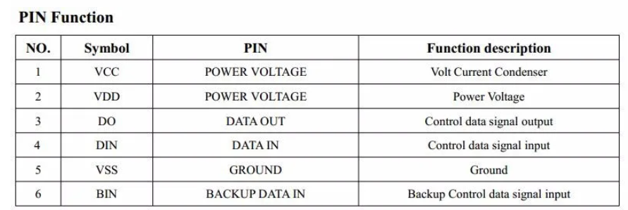
enter image description here

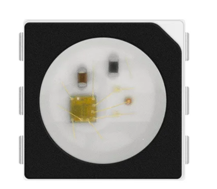
Here the pin is called “Volt current condenser” and it's not mentioned in the wiring diagram. But the resistor and capacitor seems to be embedded inside the plastic package:

enter image description here

enter image description here

I will try to unsolder the actual LED and solder it with wire (without PIN 1 connected). If this works, it might mean that the pin 1 and 2 are internally connected, right?

Then for the logic level, I might find something to stay inside manufacturer specification without adding a level shifter (as my system will use more than 30 of these boards I'd prefer to avoid more costly). The idea is that the pin of the STM32G0 used to control the data line is 5 V tolerant. This means that it can survive 5 V. So what if I use this pin in open drain mode so only GND will be set by the STM32. By adding a pull-up resistor to the data line (to 5 V) it should pull up the line if the STM32 is not pulling down.


Another edit:

I found that programming timing was also slightly different! This is maybe why these led are so cheap. The new timing is a lot slower than expected, so the refresh rate will also be slower I guess!

\$\endgroup\$

2 Answers 2

4
\$\begingroup\$

Looks like the manufacturer (WorldSemi = WS) recommends that the pin have an RC circuit connected to it (a few hundred Ω and 100nF bypass), but it's optionally left open.

enter image description here

Data line should not be internally shorted to Vcc, but if you are measuring with a multimeter you might get some odd value because there are internal diodes.

If you have only 3.3V high logic signals you are out of spec for the input to be guaranteed to work. It may work or not. If it works, it may be reliable or not. It's best to have level shifters to change 3.3V logic to 5V.

The temperature limits are similar to any other similar plastic-packaged component such as LEDs. If you have a temperature controlled iron and/or a modicom of soldering skills it won't be any or (or less) of an issue than most other parts, and not as much as some. If you approach it with a 200W Weller soldering gun then RIP WS2813.

Edit:

Looking at distributor LCSC there are at least a dozen variations of the WS2813 from WorldSemi (by suffix, E&OE - double check for yourself once you know the full part number- looks to me like the safest thing is to lay out for the RC then you can populate or not, or make the R 0Ω for direct connection:

  • WS2813E pin is NC

  • WS2813C recommended RC optional open

  • WS2813B-B recommended RC optional open

  • WS2813V-1 pin is NC

  • WS2813BV-5 Aux data OUT

  • WS2813C-V3 Aux data OUT

  • WS2813A-V1 N/C

  • WS2813A-V2 ??

  • WS2813Mini Must be connected to Vdd

  • WS2813B-RGBW Must be connected to Vdd

  • WS2813B-2121 Auxiliary data IN

  • WS2813B-Mini Auxiliary data OUT

\$\endgroup\$
1
  • \$\begingroup\$ Thanks a lot, Well I thought that all WS2813 were the same and only input voltage is different but I guess I was wrong! In my case I bought a clone from AliExpress and this may lead to all my problem. I'm still doing some testing but if this work I will come back to you! \$\endgroup\$ Commented Aug 14 at 17:46
0
\$\begingroup\$

First I found two datasheet from the same manufacturer online

The ones I found are from two different manufacturers: Normand LED and World Semi.

If the letters "WS" in the WS2813 product name represent World Semi then I'd take their datasheet as reference. Fun fact: There's no datasheet available on World Semi website, you find it from somewhere else.

I will not repeat what Sphero said in his answer, but I can see the slightest risk of having the LED (or the entire circuit) not working without knowing what version or from what manufacturer it is. The Normand LED datasheet clearly states that the circuit may not work if the pin-1 is connected somewhere in the circuit.

\$\endgroup\$

Your Answer

By clicking “Post Your Answer”, you agree to our terms of service and acknowledge you have read our privacy policy.

Not the answer you're looking for? Browse other questions tagged or ask your own question.