0
\$\begingroup\$

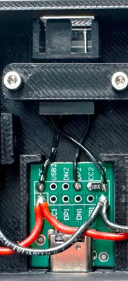
I would like to replicate this project

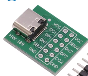
which uses this USB-C breakout board.

It's an interface box used to adapt an AC Infinity fan controller, which uses a proprietary “protocol” (UIS) over a USB-C plug, to PWM 4 pin.

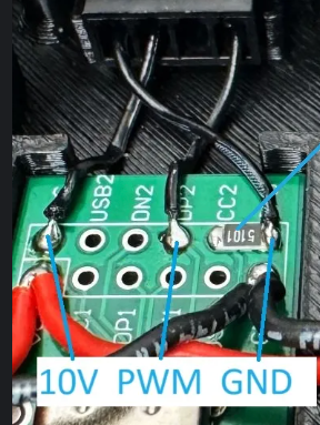
enter image description here enter image description here enter image description here

The designer states:

"Please note that I've only populated CC2 <> GND in my setup. Due to this reason you must plug the USB-C cable in the right orientation. If you plug it in the wrong orientation, the PWM output will be at 100% or in other words at 10 V."

I would like to improve that in my build.

As per my basic understanding, it should be enough to also connect CC1 to GND (via a resistor) to fix this.

But is this actually the case/enough?

Would I then also have to connect the PWM pin to DP1 as well?

Or maybe someone even knows AC Infinity's “UIS” and can tell if it's not possible at all to fix this, due to the fact that it's proprietary? (Unfortunately, the designer didn't state if this might be the case or if he was just fine with this “flaw” and left it like it is without bothering too much about it :)

Maybe someone could help me out with this.
Thanks

\$\endgroup\$

1 Answer 1

3
\$\begingroup\$

If you don't know how the remaining wires are used, it's impossible to know how to extend it. You need to ask the project designer for schematics or documentation.

Under normal Type-C environment, flipping the plug will use the other CC and the other set of USB2 wire pairs. So what you describe by using the other set of CC and DP pins would work if standard USB-C cables are used with standard devices.

So it depends on the other device as well, not only this device. And it also depends on the cable between the devices - in standard Type-C cable, only one CC wire is passed through, the second CC wire isn't, it may be left off or used to power an e-mark chip in the cable, so it may not be available for custom purposes, depending on the custom purpose required.

However it is a very bad idea to repurpose a standard connector for custom purposes like this. Connect that to a standard Type-C device accidentally and it's fried.

\$\endgroup\$
3
  • \$\begingroup\$ Sure, I get your point. But the proprietary part was introduced by the manufacturer, not the designer of this "Interface box". I'm not aware of any documentation or schematics published by the manufacturer. In the yt video which he also attached you can see that he used standard USB-C cables to connect this box to the controller, so this works fine. Just the PWM part does work in one plug orientation only, also shown in the video :) If connected the wrong way the 4 pin get's the full power - 10V in this case. \$\endgroup\$
    – Moe
    Commented Aug 19 at 6:24
  • \$\begingroup\$ I agree, in general it's bad that the manufacturer repurposed an USB-C plug for this... But as far as I understand from your reply and the info from the video, etc.: If I additionally connect CC1 -> GND and DP1 to the PWM pin of the 4 Pin connector it should work in both orientations. \$\endgroup\$
    – Moe
    Commented Aug 19 at 6:24
  • \$\begingroup\$ @Moe In theory, yes. But since it is not standard use, anything could happen. \$\endgroup\$
    – Justme
    Commented Aug 19 at 6:38

Your Answer

By clicking “Post Your Answer”, you agree to our terms of service and acknowledge you have read our privacy policy.

Not the answer you're looking for? Browse other questions tagged or ask your own question.