0
\$\begingroup\$

I am working on PWM control with a Raspberry Pi Pico and came across the term "Slice," for which I am unable to find a proper definition on the internet.

A quick search gives "Slicing in pulse width modulation (PWM) refers to the ability to drive multiple PWM output signals from a single slice. For example, the RP2040 PWM block on a Raspberry Pi Pico has eight slices, each of which can drive two PWM output signals. This gives a total of 16 controllable PWM outputs."

Does a slice represent a single GPIO pin? What is a slice?

\$\endgroup\$
2
  • \$\begingroup\$ That must be a feature specific to Pico. Have you read Pico documentation on PWM? Usually manufacturer documentation explains the MCU features and how to use them. \$\endgroup\$
    – Justme
    Commented Oct 29 at 7:03
  • 1
    \$\begingroup\$ You need to cite the source of the words quoted. \$\endgroup\$
    – Andy aka
    Commented Oct 29 at 10:02

2 Answers 2

2
\$\begingroup\$

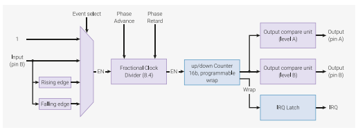
The RP2040 datasheet section 4.5. PWM defines what is meant by a slice. Some relevant parts from that data sheet section:

The RP2040 PWM block has 8 identical slices. Each slice can drive two PWM output signals, or measure the frequency or duty cycle of an input signal. This gives a total of up to 16 controllable PWM outputs.

Figure 103. A single PWM slice. RP2040 PWM slice block diagram

Which shows that a slice has:

  • One up/down counter
  • Two output compare units. Each output compare unit can drive a different GPIO output pin, and have a different duty cycle.

Datasheet table 515 shows the mapping of PWM channels to GPIO pins on RP2040. This shows all 30 GPIO pins can be used for PWM output, with 7 out of the 8 slices having two GPIO pins which can be selected for a particular PWM output channel:

RP2040 mapping of PWM channels to GPIO outputs

\$\endgroup\$
1
  • 1
    \$\begingroup\$ And note that this is terminology specific to the RP2040; it is not something with any meaning in general. \$\endgroup\$
    – Hearth
    Commented Oct 29 at 12:26
1
\$\begingroup\$

The RP2040 has 8 slices considered as a section. Each section has the ability to produce two PWM signals. That is two separate signals.

The first slice has PWM 0A and PWM 0B .

Note this sequence go up to 8 slices like this:

PWM 1A - PWM 1B
-
-
-
PWM 7A - PWM 7B

It therefore has 16 PWM signals from a single RP2040 PWM hardware.

The 16 PWM outputs require 16 GPIO pins.

You can configure how many slice you want to use. For example, if you only use 10 PWM signals you configure only 5 slices.

By using this hardware block through coding you can generate 16 types of PWM signals which can use different peripherals or for same peripheral.

Say you have one data signal (PWM) that consists of data corresponding to alternate 6 LED blinking like addressable LEDS.

For 30% duty cycle(IP) - LED 1 3 will glow.
For 50% duty cycle(IP) - LED 2 4 will glow.
For 70% duty cycle(IP) - LED 5 6 will glow.

You have one input signal with six output signals from the RP2040. We can do this operation based on the condition with slicing.

\$\endgroup\$

Your Answer

By clicking “Post Your Answer”, you agree to our terms of service and acknowledge you have read our privacy policy.

Not the answer you're looking for? Browse other questions tagged or ask your own question.