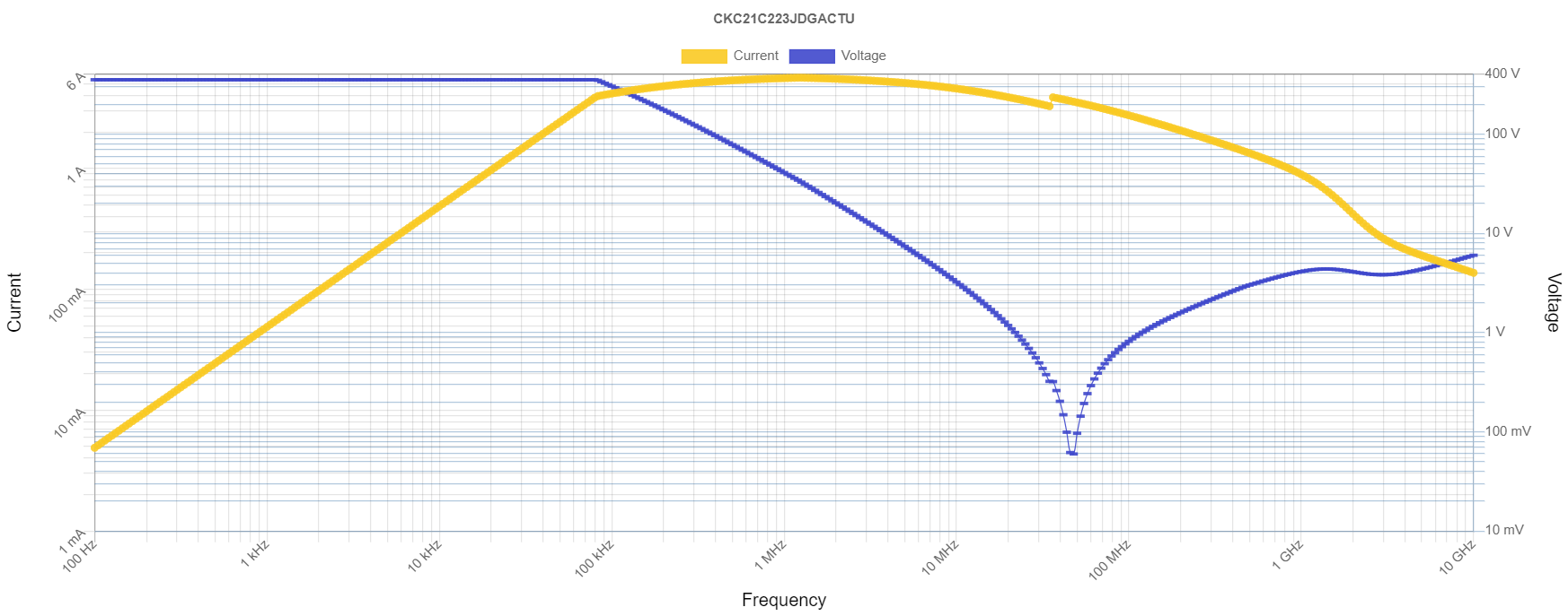
Here's the estimation process I use.
Consider a resistor of the same chip size, and its rating. The capacitor will tend to be thicker, and the material, lower thermal conductivity than the Al2O3 used in resistors.
Taking half the power rating of an equivalent chip resistor, seems safe enough.
Then consider the ESR or Q. ESR is generally extremely low, to the point it can almost be ignored (which is a sometimes perverse thing already: for example, 10nF C0Gs placed side-by-side in parallel will resonate with each other, with the mere 5nH or so loop inductance between them!). Obviously for ripple current purposes, we must still take stock of that figure, and express the tolerable voltage or current vs. frequency.
Generally this suggests rated voltage (AC if given, or DC peak-to-peak), up to some 100s kHz at least, if not MHz still, and then dropping off above there as the current limit takes over.
There will be some additional derating at high frequencies (1s to 10s MHz onward) where skin effect reduces effective cross-section of the device (basically, think in terms of the solid metal end-caps shielding current flow to inner layers, thus ESR rises as \$\propto\sqrt{f}\$). This should be evident from the ESR as given; just a reminder that it's not perfectly straight asymptotes defining the operating limits.
You'll have a damned hard time violating a rating like that, where low ripple is required, as in a DC supply filter. This does suggest some potential optimizations, like using a C1 || (L+C2) motif to put a notch in the transfer function: the LC multiplies the ripple voltage from C1 onto C2, making C2 many times more effective -- but only near the resonant frequency, so this is only applicable to fixed-frequency converters where the notch(es) can be placed on Fsw and harmonics. And obviously you need a high-Q inductor to do that; but, why not just make a better filter overall using a poorer quality L with bulkier C's instead?
This is in part why type 2 dielectric are most popular at low voltages, and (still fairly boutique, but attractive when size is higher priority than cost) poled electrets at high voltages (~500V DC link, etc.).
Type 2 (normal, un-poled) are poor at high voltages for a couple of reasons: ceramic in general get expensive when you need bulk values and energy storage; and high-voltage types have fewer fatal dielectric defects, meaning they can handle a much higher electric field strength: which is to say, the C(V) curve you get on a, say, 250V part, is wildly more depressed than that of a 16V part -- you just can't get parts of any reasonable value-density.
But where applicable, the relatively low ripple of a DC filter means lossy types like type 2 ceramic, electrolytics, and powdered-iron inductors, are quite acceptable.
On top of that, you generally need losses in DC filters anyway, to make them insensitive to source/load impedance variations, which makes lossy types further attractive.
Somewhat unrelated, but handy in general: think of polymer electrolytics as low-voltage film caps. They're available in a range of ESRs, but the lowest are very comparable to DC-link type polypropylene film caps, scaled for low voltages. (Films don't scale to low voltages, because the film has to be so thin and wide, it's impossible to get adequate yield. Kinda C0G has the same problem below 100V or so, hence values like 100nF are "large" for it.)


