4
\$\begingroup\$

I am thinking of using a microcontroller to do engine control on a gasoline motor (a 1950's Briggs and Stratton) and using its own accessory magneto to supply the microcontroller.

My first idea is to use a supercapacitor to supply the 5V to the electronics.

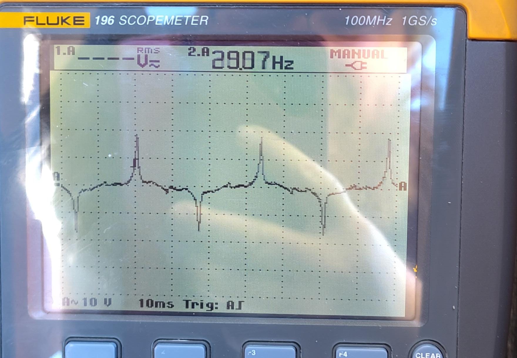
Sadly, the accessory magneto supplies a rather noisy voltage, with short (timewise) peaks at +-25V. Not supercapacitor compatible, obviously.

With peaks at ~+-25V

I need capacitors -> (regulation) -> supercapacitor -> load.

Because the magneto is quite weak and there are also some lightbulbs in parallel in the circuit, I do not want to only clip the peaks (with an SCR, Zener or varistor or others) but accumulate the spike energy some way or anothe, to use it later in the microcontroller.

I am looking for ideas that are more efficient or robust than simply an entry capacitor with high voltage

\$\endgroup\$
1
  • \$\begingroup\$ You say there are lightbulbs in parallel. I would consider replacing those with lower-power LEDs if possible, to reduce load and free up current for your electronics. \$\endgroup\$ Commented Nov 16 at 8:30

4 Answers 4

3
\$\begingroup\$

Obvious thing to try is a full wave bridge rectifier-> capacitor-> buck converter. But you might need to add a shunt limiter (TVS, power Zener etc.) so the voltage does not go sky-high when the bulb is removed or burns out (probably destroying the buck converter).

Anything that will power an incandescent bulb has plenty of power for any computation and display you might need. I have a two-core processor running at 240MHz with a ~100mm 480x480 IPS LCD display, backlight at full brightness and it draws less than 1W with Wifi and BT radios turned off. A small incandescent bulb is maybe 5W.

\$\endgroup\$
2
\$\begingroup\$

Try this circuit:

schematic

simulate this circuit – Schematic created using CircuitLab

The values aren't critical and you can make adjustments as needed. If you need higher efficiency, you can put a switcher in place of the LDO reg at the expense of reduced headroom for voltage regulation. Also, you can use a 3.3V regulator if that's what your MCU needs.

If you measure high-voltage high-frequency spikes after the pi filter, a TVS or 25V Zener across the regulator input may be a good protection measure. But I believe the spikes will be substantially reduced and this will not be needed.

\$\endgroup\$
2
\$\begingroup\$

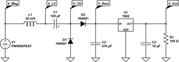
To limit the peak current you can place an inductor in series with the magneto.

To use both polarities of the magneto, you can use a capacitive coupled rectifier and get some unregulated DC voltage with a lot of ripple at C2.

In this example I assume a maximum current of 50 mA at 5 V MCU supply, which is implemented as R1 .

In this demo circuit a linear regulator U1 is used to produce a stable voltage for the MCU. However, a switching regulator would be a much better solution.

The software should be aware of the sloppy rising supply voltage, so a long delay at boot time should wait until the voltage is stable or a dedicated power good signal is used.

The values for L1 and C1 are chosen to produce enough voltage in front of the regulator at 50 mA load current. If more current is needed, you should reduce the value of L1 and increase the value of C1.

schematic

simulate this circuit – Schematic created using CircuitLab

\$\endgroup\$
2
  • 1
    \$\begingroup\$ There is already an inductor, the magneto itself. \$\endgroup\$
    – fraxinus
    Commented Nov 16 at 8:55
  • \$\begingroup\$ Just as a little addendum, if you do end up using a 7805, probably worth putting a heatsink on it/doing something about cooling, especially if you are running it in close confines to an engine, they tend to run a bit hot (at least the cheap versions I've used do) \$\endgroup\$
    – limequokka
    Commented Nov 17 at 8:29
0
\$\begingroup\$

You're overthinking it. Once the magneto is connected to a capacitor (or capacitor bank), including a supercapacitor, there will not be such big voltage spikes because sudden energy pulses will go into charging the capacitor(s) instead of suddenly raising the voltage.

It's likely your microcontroller only needs a tiny trickle of power and the capacitor(s) will charge all the way to 25V, so to limit the voltage supplied to the microcontroller, I suggest a high-value resistor (e.g. 10k or more) and a Zener diode clamp. This is based on the assumption that your microcontroller uses very little current. Otherwise, a different circuit could be more appropriate.

\$\endgroup\$

Your Answer

By clicking “Post Your Answer”, you agree to our terms of service and acknowledge you have read our privacy policy.

Not the answer you're looking for? Browse other questions tagged or ask your own question.