Like the title suggests, I am trying to measure the irradiance of a laser. This is done using an integrating sphere and a photodiode. The light that enters the integrating sphere has to travel through a plasma. This plasma is created via a burst of light, the burst consists of fifty pulses which present as a fifty impulse responses when viewed using an oscilloscope (something like | | | | | where each '|' is a pulse). All together, there are two photodiodes, one that captures the burst before the plasma that is used as a reference (photodiode A), and one photodiode that is used to measure the irradiance after travelling through the plasma (photodiode B).
Note I have no idea how the circuit for photodiode A is done because I cannot take it apart without messing up the setup entirely.
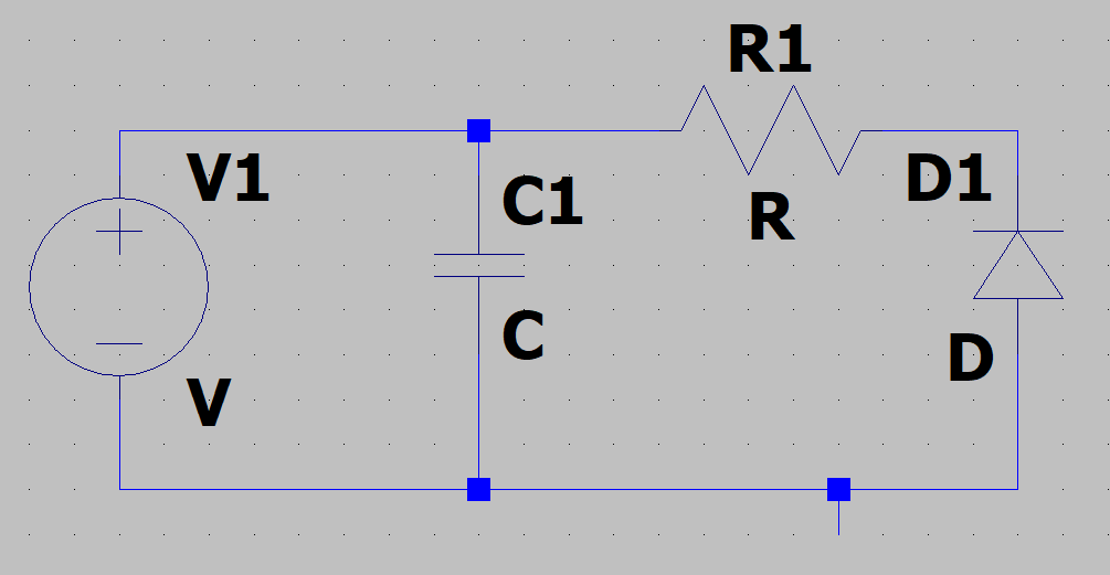
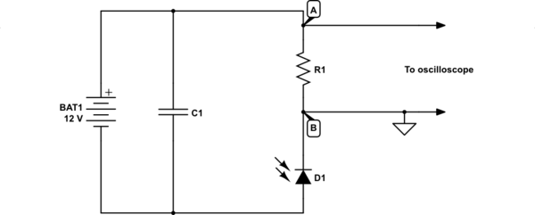
The circuit I am using for photodiode B is very simple, a 12VDC battery connected to a capacitor which is in parallel with a resistor. The capacitor goes straight back to ground and the resistor is in series with the photodiode which is in series with a cable that I used to connect to the oscilloscope.
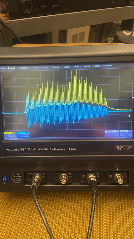
The interesting part is that when I view the burst through photodiode B, the shape on the oscilloscope is sinusoidal with peaks corresponding to the peaks from the reference. This doesn't make any sense to me because from previous trials the result from photodiode B looked almost exactly like the result from photodiode A, just a bit smaller in amplitude. This started happening after I had to repair the circuit because someone accidentally broke it.
Any help or suggestions as to the root cause of the issue would be greatly appreciated.
Edit: Wavelength 1030nm, iirc resistance 100 Ohm, capacitance I don't know, pulse duration roughly 350fs repetition frequency maybe 5nm but I'm not sure, no idea what the photodiode model is. I was not the one who built it originally.
Circuit, the little line pointed down is where I connected the oscilloscope:

Example from oscilloscope, yellow is reference, blue is photodiode B:


