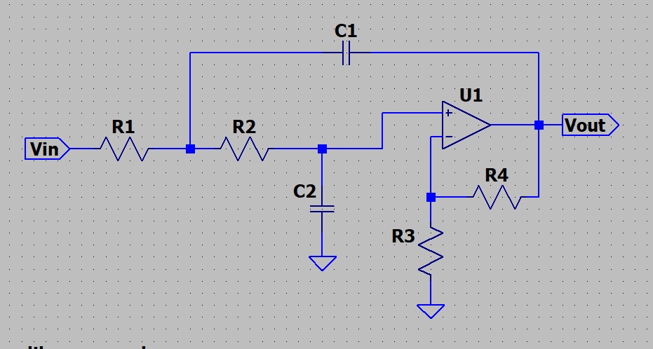
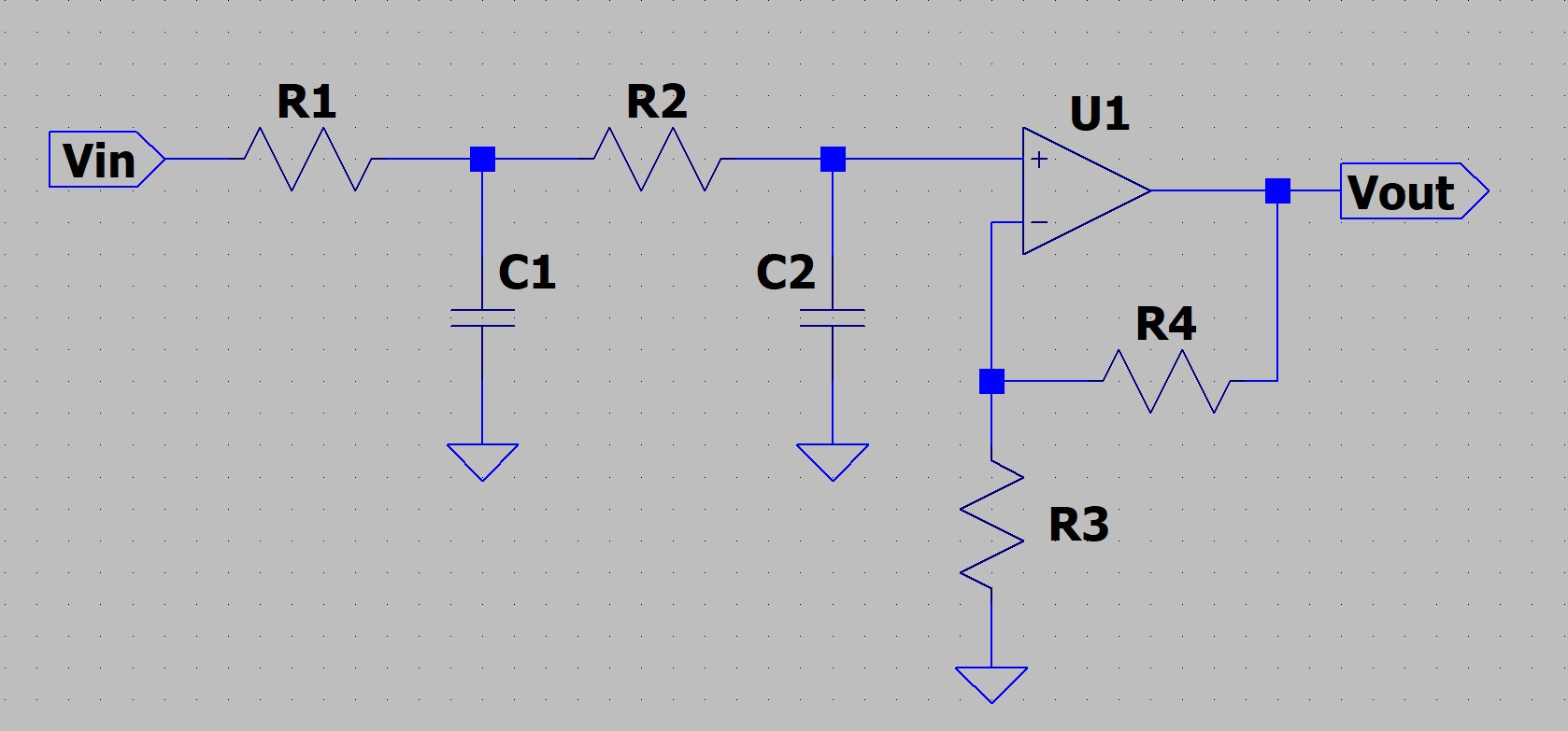
Your statement that the two have the same transfer function is false. This can be seen by inspection of their simplified equivalents:
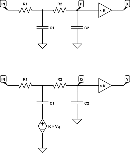
simulate this circuit – Schematic created using CircuitLab
Here \$K=1+\frac{R_4}{R_3}\$ is gain of the op-amp section, so that:
$$ V_X = K \times V_P $$
$$ V_Y = K \times V_Q $$
The Sallen-Key design (bottom) applies potential \$K\times V_Q\$ to the bottom end of C1, while the other applies 0V, a difference which would be very evident in their respective transfer functions:
$$ X(s) = \frac{K}{1+s(C_2R_2+C_2R_1+C_1R_1)+s^2(C_1R_1\cdot C_2R_2)} $$
$$ Y(s) = \frac{K}{1 + s \left( C_2 R_2 + C_2R_1 + C_1 R_1 (1 - K) \right) + s^2(C_1 R_1 \cdot C_2 R_2) } $$
They do not have the same transfer functions, but the difference is subtle; only the coefficient of \$s\$ in the denominator changes, with its \$C_1R_1\$ term being scaled by \$1-K\$.
For the two functions to be equal, \$Y(s)=X(s)\$, we require coefficients of \$s\$ and \$s^2\$ in each to be equal:
$$
\begin{aligned}
C_{X1}R_{X1} &= C_{Y1}R_{Y1} \\ \\
C_{X2}R_{X2}+C_{X2}R_{X1}+C_{X1}R_{X1} &= C_{Y2}R_{Y2}+C_{Y2}R_{Y1}+C_{Y1}R_{Y1}(1-K) \\ \\
\end{aligned}
$$
You have some flexibility with the cascaded RC design, in that the factor \$K\$ is arbitrary, not changing the position of poles in any way. You can set its \$K\$ to whatever you want in your endeavour to make \$X(s)=Y(s)\$. However, \$K\$ for the Sallen-Key design is constrained to \$K\ge 1\$, and changing it does alter poles.
I haven't examined in detail the feasibility of obtaining \$X(s)=Y(s)\$, but I think there are severe constraints on candidate values of resistance, capacitance and gain \$K\$ that can achieve such equality. There are transfer functions realisable with cascaded RC filters that Sallen-Key cannot achieve, and Sallen-Key can implement transfer functions that cascaded RC filters cannot. Consequently, the question of pros and cons seems somewhat moot, superseded by a consideration what one can do that the other cannot and vice-versa.
Having said that, there are differences not related to the transfer function that deserve mentioning. The first is that the cascaded RC design doesn't (technically) need an amplifier. As long as the following stage doesn't load node P, it can have whatever features you desire; it could be a power stage, or an audio compressor, or another low-pass filter for a third pole. The Sallen-Key design mandates an op-amp, and precludes you from shoe-horning in additional roles for it.
The second difference that comes to mind is that the output of the op-amp in the Sallen-Key design is loaded by its own feedback. This feedback path is a sink/source of current that the op-amp output must provide, while also "driving" whatever comes next. While this isn't usually considered in academic material describing Sallen-Key, in practical designs you must ensure that the op-amp can sink and source both feedback and load current simultaneously. The amplifier following a cascaded RC filter has no such feedback load to worry about.

