0
\$\begingroup\$

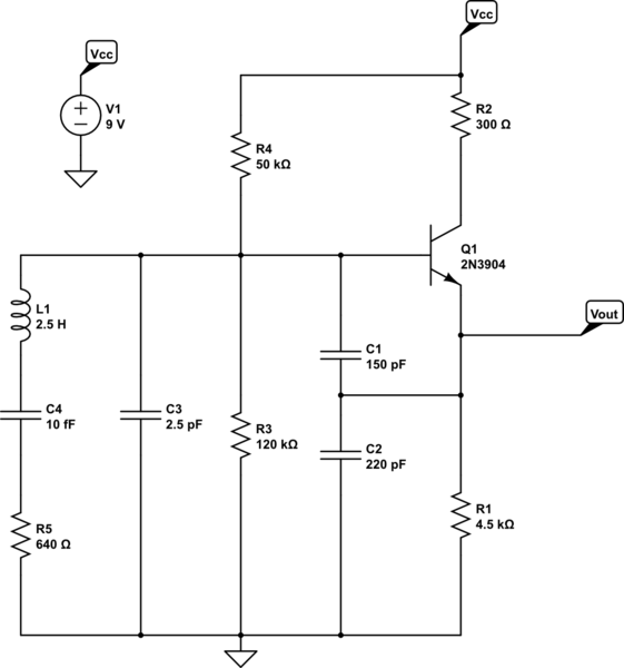
I am currently attempting to simulate as well as design a Colpitts oscillator using a quartz crystal operating at 1 MHz.

I seem to be struggling with my output which is more of a sawtooth wave than a sinusoid (which is ideally what I am aiming for.)

For my design I am using a 2N3904 BJT and a HC-49U crystal. I have attached my LT spice simulation (rather, designed it with the webpages tool, but I use LTspice.) Note that for the simulation I used the electrical equivalent of the quartz crystal which is the RLC components in parallel with the other capacitor and calculated the values such that the frequency is \$\frac{1}{2\pi \cdot \sqrt{LC}}\$ where \$C = \frac{C_3\cdot C_4}{C_3+C_4}\$.

I have watched numerous videos, made many slight changes to component values, and reviewed the datasheet of the BJT for biasing assistance.

However, for some reason, my oscillator is still not sinusoidal at the output when I do a transient sweep set for 100ms.

Some (though not all) resources I used when designing:

schematic

simulate this circuit – Schematic created using CircuitLab

\$\endgroup\$
11
  • \$\begingroup\$ One problem is that you want \$C_1\gg C_2\$ because the base-emitter swing is controlled by the ratio of these two capacitors. You want the swing to be relatively small in order to get a more sinusoidal output. Of course, \$C_1\$ must be much greater than the input capacitance to the BJT. (I think you achieved that.) \$\endgroup\$
    – jonk
    Commented Oct 19, 2022 at 7:18
  • \$\begingroup\$ So Chris? Consider changing \$C_1\$ to \$2.2\:\text{nF}\$. \$\endgroup\$
    – jonk
    Commented Oct 19, 2022 at 7:34
  • 1
    \$\begingroup\$ Thank you for your assistance Jonk! I made the change in LT Spice and the simulation looks much better. I'll be testing it this afternoon on the o-scope to see how the real life results look. \$\endgroup\$
    – Chris
    Commented Oct 19, 2022 at 15:55
  • \$\begingroup\$ Keep in mind that value I suggested might be a little high-handed. So also consider something about half that much, as well. And thanks for letting me know that it at least simulated better. :) \$\endgroup\$
    – jonk
    Commented Oct 19, 2022 at 18:09
  • \$\begingroup\$ Excellent news! I tested it with the 2.2 nF on an o-scope and it looks sinusoidal! Thanks again for your help. Perhaps I can ask you one more question, any ideas why the o-scope would say the Vpp is 19.6v when the simulation shows Vpp is about 4.4v? I made sure the probe was set to 1x and not 10x as well. \$\endgroup\$
    – Chris
    Commented Oct 19, 2022 at 18:25

1 Answer 1

1
\$\begingroup\$

The problem I see is that you have \$C_1\$ way too small by comparison with \$C_2\$. I think your value for \$C_2\$ is fine. But I'd increase \$C_1\$ so that \$5\cdot C_2 \le C_1 \le 10\cdot C_2\$. This is because the base-emitter swing is controlled by the ratio of these two capacitors. The swing needs to be relatively small in order to get a more sinusoidal output, too.

Of course, both capacitors must be much greater than the input capacitance to the BJT. But I think you achieved that.

I'd recommend at least considering the idea of adding a little emitter degeneration (to overwhelm \$r_e^{\,'}\$ and further improve the sinusoidal appearance at the output) by inserting a resistor between the BJT emitter and the \$C_1\$, \$C_2\$, \$R_1\$ node. Not a large value. Maybe \$10\:\Omega\$? (Plus or minus.) That may slow down the oscillator startup a little and may even shut it down completely. But if you get it right it may do wonders for the THD (which is otherwise distorted by a more widely varying, signal driven, open loop gain.)

\$\endgroup\$

Your Answer

By clicking “Post Your Answer”, you agree to our terms of service and acknowledge you have read our privacy policy.

Not the answer you're looking for? Browse other questions tagged or ask your own question.