3
\$\begingroup\$

I am doing a homework that I got yesterday and it concerns calculating phase currents and a neutral phase current. 3 phase it is. Three individual charges, each on their own phase and a shared 3-phase charge. L2 phase charge has a power factor of cosΦ 0,90.

Homework goes like this:

We have a house with 400/230V grid and in a certain point of time it has charges like these:

L1 - Lightning and heating 3kW L2 - Lightning, heating and motors 4,5kW, power factor cos Φ =0,90 L3 - Lightning and heating 1,5kW.

Additional to those we have a 3-phased boiler that charges our grid with 6,0kW. Calculate phase currents and neutral phase current.

I tried to calculate this over 10 hours now, but for some reason I didn´t "get" the idea of it. This is what i have thought of it this far:

P1 = 3kW + 2kW (latter is 1/3 of that 3-phased boiler) = 5kW

P3 = 1,5kW + 2kW (latter is 1/3 of that 3-phased boiler) = 3,5kW

P2 seems like the "trap" of this task. As far as I have understanding, active powers can´t be summed together in this case. I will get back to this later, first I calculate currents of P1 and P3:

I1 = P1/Uv = 5000W/230V = 21,74A

I2 = P3/Uv = 3500W/230V = 15,22A

Two out of four currents calculated. Now we need the I3, so we could make vectors on paper and solve neutral phase current In.

If I calculate I2 like this, would it be right?

First I name both charges, so I don´t mix them up. P2x is the 4500W charge and P2y is the 2000W charge (1/3 of that 3-phased boilers power)

I2 = (P2x/Uv*cosΦ 0,9) + (P2y/Uv)

= (4500W/(230V*cosΦ 0,9)) + (2000W/230V)

= 21,74A + 8,695A

= 30,435A

Now I have all three currents that I need to solve neutral phase current.

I1= 21,74A

I2= 30,435A

I3= 15,22A

I decided to make an vector drawing out of it.

First vector is the I1 and it goes along L1, because power factor of it is 1. Second vector will be drawn continuing from L1 toward L2.

If there would be no difference in power factor, the angle would be 60°. This time we have it, and it is as much as cosΦ 0,90, as a degrees, it is 25,84°. We will subtract it from that basic angle 60°.

60° - 25,84°= 34,16°

Last current left, until we can measure the neutral phase current. We draw it in an angle of 60°, because once again power factor is 1.

Phew... Now I measure, with shaking hands. And I get 4,5A for a neutral phase current.

Somehow I just feel I didn´t get the exact right answer out of it. There is something that I don´t understand and I think it concerns calculating Phase L2:s active powers.

At first I thought that I could calculate current powers together and solve current out of it. Like this:

P2 = 4500w+2000w = 6500W

I2 = P2/(Uv*cosΦ0,90)

= 6500W/(230V*cosΦ0,90)

= 31,4A

I just felt it can´t be right, because there is kind of two different idle and active powers and from those I should get apparent power. S² = P² + Q² wouldn´t apply straight and true. From combined apparent power I could solve the phase current of I2.

I know that I am not stupid, but a slow learner. Half of our class won´t even try to do this, because they have given up, even if they want to learn. Our teacher rush things forward and he won´t be interested to explain things better.

Yesterday I tried to think of this homework like 6 hours and approximately the same amount today too. If and when I learn this, then I will surely teach it to other people in our class too.

\$\endgroup\$
1
  • \$\begingroup\$ I presume you mean lighting above? \$\endgroup\$
    – copper.hat
    Commented Oct 19, 2014 at 6:51

3 Answers 3

2
\$\begingroup\$

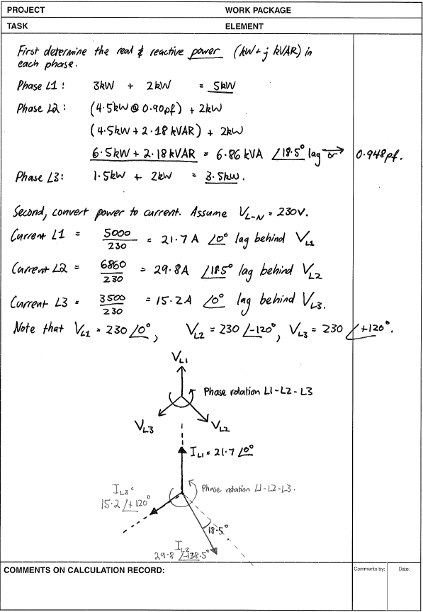
No guarantees as to correctness, but this shows the general method.

  1. Find the real and reactive power flowing in each phase.
  2. Determine the current flowing in each phase, including the angle between phase current and phase voltage.
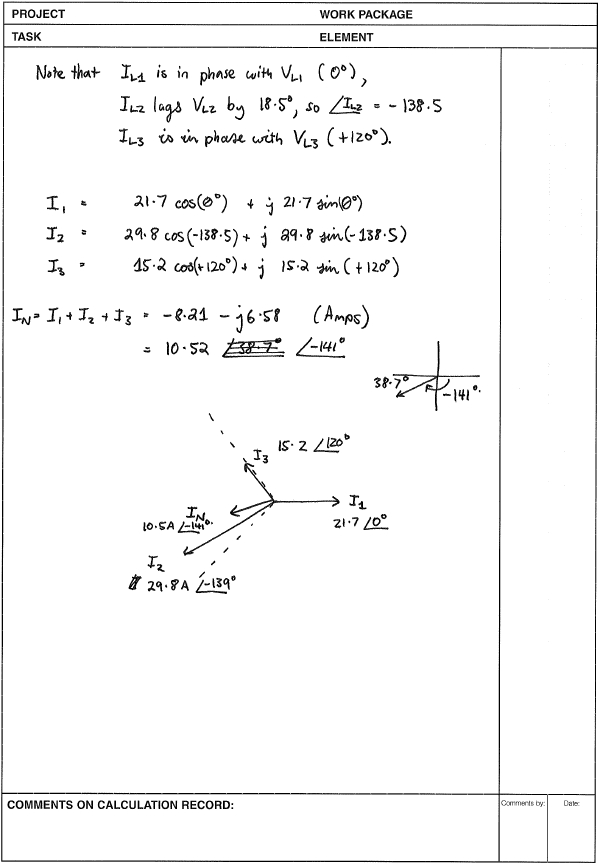
  3. Add all currents vectorially - real and imaginary components. A diagram helps.

By convention, phase rotation is anti-clockwise. An inductive load will make the current lag behind the voltage. (Remember, inductors resist changes in voltage dv/dt.)

Diagrams below are not to scale.

enter image description here

enter image description here

\$\endgroup\$
7
  • \$\begingroup\$ Also, where I come from, the phases are named 'red, white, blue'. None of this L1, L2, L3 or black, gray, brown nonsense. ;) \$\endgroup\$ Commented Feb 20, 2014 at 10:28
  • \$\begingroup\$ Red, white, blue? You must live in America. \$\endgroup\$ Commented Feb 20, 2014 at 11:00
  • \$\begingroup\$ @ConnorWolf: Actually, I live in Australia. Per our wiring rules (AS/NZS 3000 §3.8.1) the recommended colours for actives are 'Red, white, or dark blue for multi-phase'. The European cable colours (black, gray, brown) are also permitted provided you don't combine the two colour schemes in the same cable. \$\endgroup\$ Commented Feb 20, 2014 at 11:33
  • \$\begingroup\$ @ConnorWolf: By which I mean to say that I like Red, White, Blue more than L1, L2, L3, and get off my lawn! :) Also, in Australia black is always the neutral and white is a phase, whereas in the USA black is an active and white is the neutral... remind me to be double careful when working with US wiring. \$\endgroup\$ Commented Feb 20, 2014 at 11:34
  • 1
    \$\begingroup\$ Li-aung Yip, i did not get how you calculate the IN with I1, I2 and I3 ready? Can you please help me in this? \$\endgroup\$
    – user56481
    Commented Oct 19, 2014 at 6:18
1
\$\begingroup\$

OK, I think I've got it....

  • Power 1 = 3.0kW + 2kW at 230V means current is 21.74A (5kW divided by 230V)
  • Power 2 = 4.5kW (PF = 0.9) + 2kW means current needs to be vectorially added
  • Power 3 = 1.5kW + 2kW means current is 15.22A (3.5kW divided by 230V)

Current in phase 2 - there is clearly "real" current to generate power and this is: -

\$\dfrac{4.5kW+2.5kW}{230V} = 28.26A\$.

There is also reactive current in phase 2 due to the 0.9 power factor but first, the real current from the 4.5kW load is 19.57A. Now we need to calculate the total current in the reactive load: -

\$\dfrac{4500W}{0.9\times 230V}=21.74A\$

If we know total and real currents, pythagorus will yield the imaginery in the 4.5kW load: -

\$\sqrt{21.74^2-19.57^2} = 9.47A\$

This means that the total current in phase 2 is: -

\$\sqrt{28.26^2+9.47^2} = 29.80A\$

Given that you have the total current in phase 2 you can calculate the phase angle of phase 2 which is \$\cos^{-1}(\frac{28.26}{29.80}) = 18.5º \$ from the real axis. The net power factor of phase 2 is \$\frac{28.26}{29.80} = 0.948\$ i.e. a bit closer to unity because of the resistive 2kW load on phase 2.

To calculate the neutral current, you need to add these three currents up vectorially with phase 2 current not being 120º to phase 1 but 138.5º to phase 1.

There are probably quicker ways but I'd split all 3 currents into their respective vector quantities such as A + jB and add the 3 A terms and add the 3 B terms.

Hope this helps.

\$\endgroup\$
0
\$\begingroup\$
> L2 @ 0.9 pf means 25.8 deg lag with Pvar=4.5/0.9= 4.94kVar or 
> L2=4.5kW @120 deg , 0.494kW @ 145.8 deg L1= 3kW @ 0deg L3=1.5kW @ -120
> deg Neutral 4.5 -3-1.5=0 + j0.5kW @ 145.8deg L1,2,3 are straight
> forward.
\$\endgroup\$

Your Answer

By clicking “Post Your Answer”, you agree to our terms of service and acknowledge you have read our privacy policy.

Not the answer you're looking for? Browse other questions tagged or ask your own question.