As a background to this project, I have taken an off the shelf bldc stator and incorporated it into a small pump, and then built my own rotor using discrete neodymium magnets. At first, everything went fine, and experimentation showed that higher magnet levels increased efficiency proportionately. I then purchased custom n52 magnets that maximized space. However, I noted that the motor then ran funny. Throwing the setup on the scope like this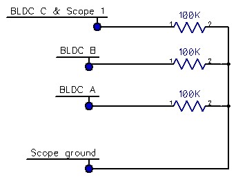
and spinning the rotor with a drill showed this odd waveform.
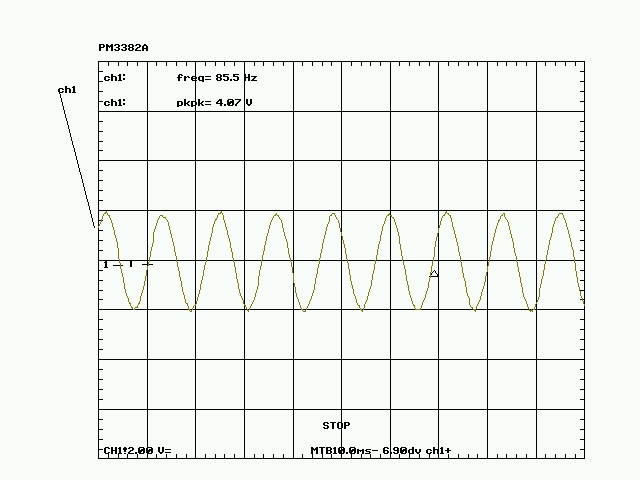
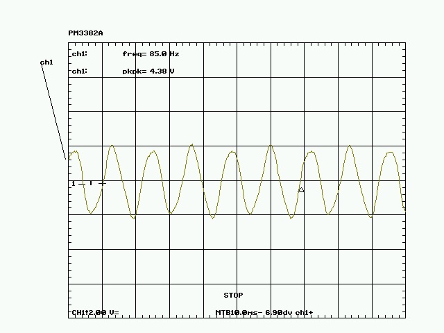 After adding a small steel core, note how this changed.
femm plots:
Showing current with steel core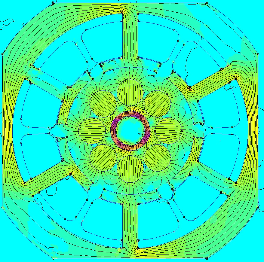
Showing current No steel core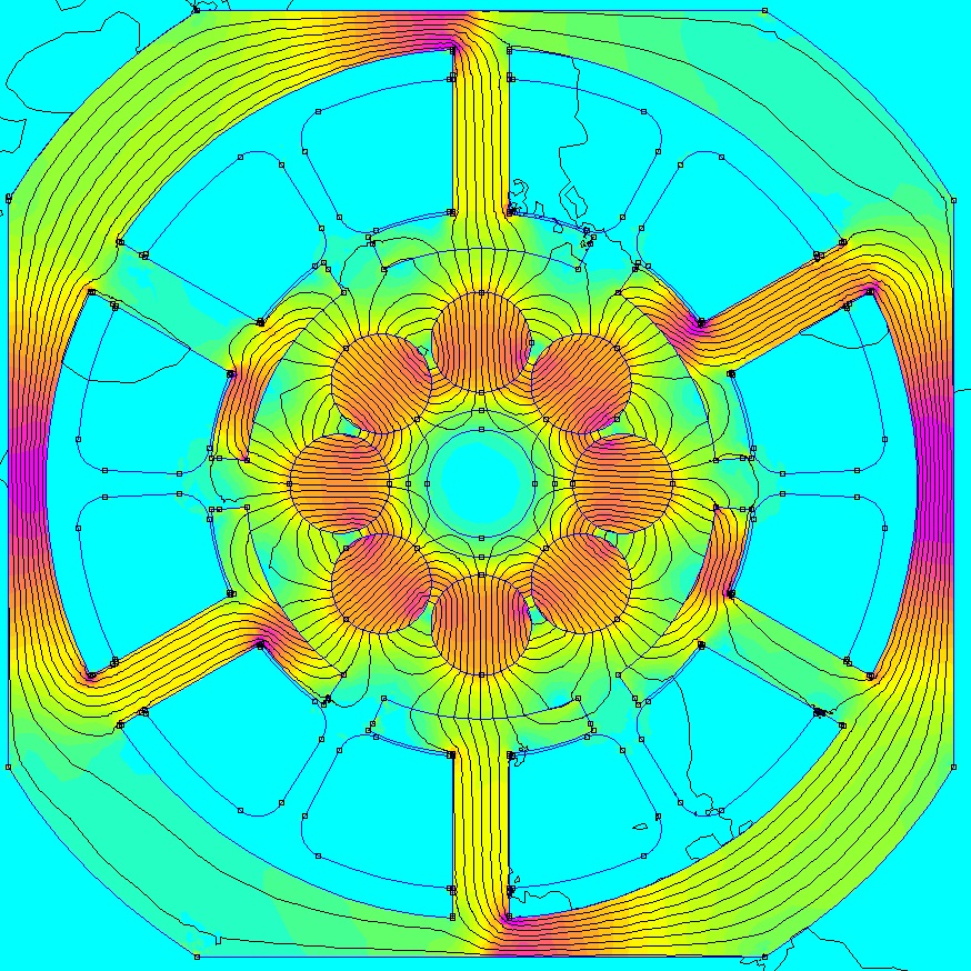
No current with steel core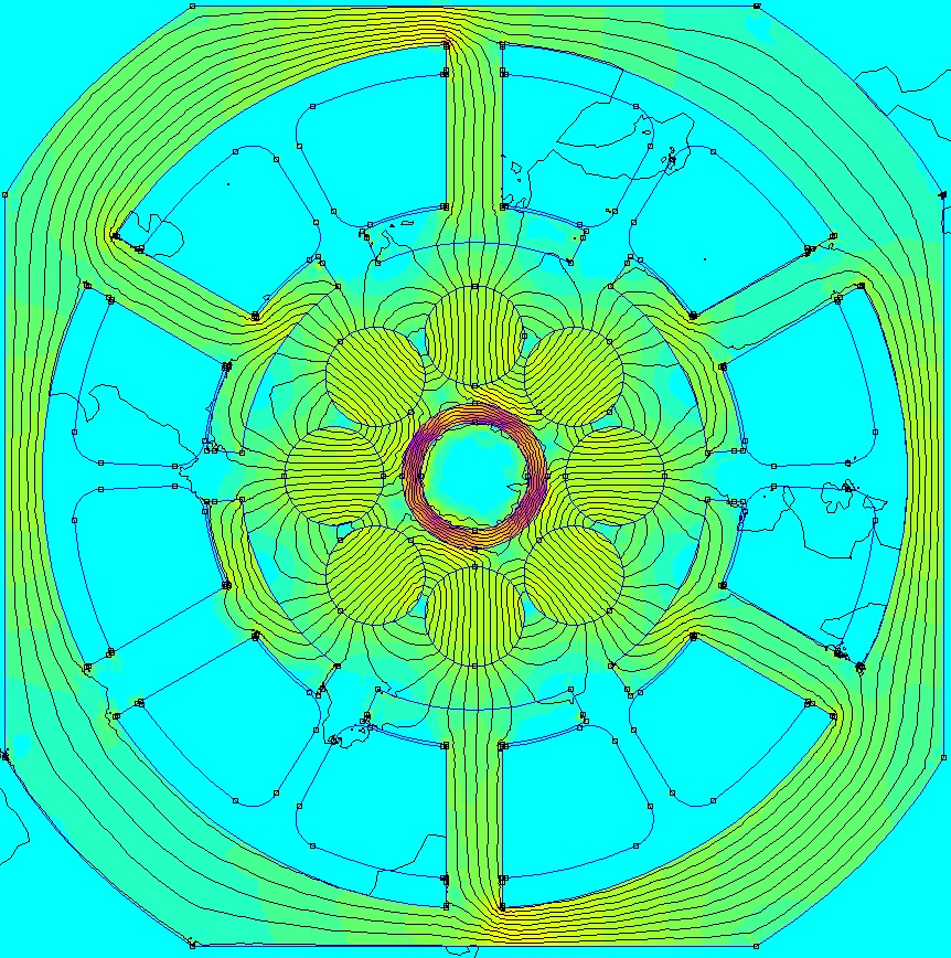
No current, no steel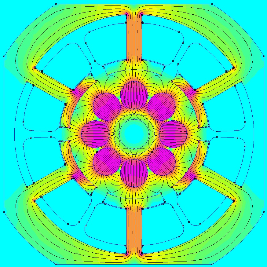
Addition: I am comparing bemf voltages produced by original rotor and replacement rotor. OE is around 5.2V@1250rpm, the handbuilt replacement rotor is around 4.05V@1250rpm
Femm plot if you want to try it yourself
Question #1. Am I dealing with eddy currents, or how could these odd scope waveforms be explained?
Question #2. I suspect that efficiency and field strength go up with steel placement, but why don't the plot field strengths seem to reflect this?
Question #3. Whats the best way to understand these plots in a way that translates to real world physical force on the shaft?
Edit: I am leaving the links to the referenced items in the answer about the coupler, but these have caused misunderstanding about the issue, so I am removing the pictures from the direct view.
