4
\$\begingroup\$

enter image description here

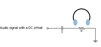
Lets say I have an audio signal with a DC offset and I want to use my earplugs to listen it clearly. Since I'm a human my hearing range is 20Hz to 20kHz. It means I need to filter very low frequency components i.e where f<20Hz. It means the cutoff frequency for the simple high pass filter circuit in my figure must be such that 1/2*piRC=20Hz. Here I need to know the impedance of the head phone (shown as R in the figure) to choose a proper capacitor.

At this point I'm confused:

My question is how can I measure this impedance? By simply using an ohmmeter? But what if it has different impedances in different frequencies? Should I apply an ac signal at a particular frequency and measure its impedance? Is headphone impedance pure resistive?

\$\endgroup\$
1
  • \$\begingroup\$ analog.com/en/rfif-components/direct-digital-synthesis-dds/… use this, it is designed to measure impedance as a function of frequency. You may also want to add a bit more power to the output since it may not be matched so well. In their datasheet, they even tell you what extra circuitry to use. How easy! \$\endgroup\$
    – HL-SDK
    Commented Nov 27, 2013 at 17:57

3 Answers 3

5
\$\begingroup\$

Relying on the headphone impedance for filtering is probably a bad idea. Different kinds of headphones will be significantly different. Even different instances of the same model of headphones can be different. The headphone impedance isn't just resistive but also reactive, and it will take some work to characterize it. Someone might plug your thing into a line input, instead of headphones, and expect it to work.

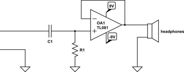
Instead, consider buffering the output. For headphones, an op-amp will do. You can, in fact, find tons of designs online for "headphone amplifiers". Some of them even use very expensive op-amps from Burr-Brown costing $50 or more, and, I'm told, these sound better than unobtanium flux linkages. Personally, I just use whatever op-amps I have in the parts drawer. Anyway:

schematic

simulate this circuit – Schematic created using CircuitLab

Now calculating C1 is easy, because you also get to pick R1. Just make it anything significantly bigger than your source impedance. Make C1 whatever you like to get the desired frequency response. The headphone impedance is largely irrelevant, because the output impedance of OA1 is so small.

\$\endgroup\$
8
  • \$\begingroup\$ whatever op-amps I have in the parts drawer so long as the GBW is beyond band of interest, and it's unity gain stable. :-) \$\endgroup\$ Commented Nov 27, 2013 at 15:16
  • 3
    \$\begingroup\$ @AnindoGhosh don't feed the audiophiles. \$\endgroup\$
    – Phil Frost
    Commented Nov 27, 2013 at 15:17
  • 1
    \$\begingroup\$ Relevant anecdote: I once had a SOT23-5 op-amp in my samples drawer, so for some audio quick & dirty buffering, I figured "How neat!". When the output consistently sounded like lions gargling with soap water, I checked the GBW. TLV2241, 5.5 KHz. Till that day, I had never thought an op amp could have a GBW that low. \$\endgroup\$ Commented Nov 27, 2013 at 15:23
  • \$\begingroup\$ Shouldn't the output of the op-amp be current limited? \$\endgroup\$
    – m.Alin
    Commented Nov 28, 2013 at 12:23
  • \$\begingroup\$ @m.Alin It couldn't hurt, but I'm pretty sure the TL082 is already specified to not self-destruct into a short. \$\endgroup\$
    – Phil Frost
    Commented Nov 28, 2013 at 12:59
2
\$\begingroup\$

I would use the nominal impedance of the headphones, and pad generously. You will need a large electrolytic capacitor, well in the hundreds of microfarads or more.

If you are after fidelity, then the filter calculations you have in mind might as well be tossed out of the window, because if you're after fidelity, speaker coupling capacitors must be seriously over-sized in order to minimize low frequency distortion. [Source: Audio Power Amplifier Design Handbook, Douglas Self].

(If you're not after fidelity, then why bother trying to achieve excellent low frequency response.)

There is an amplifier solution for avoiding the capacitor that doesn't involve obtaining a dual-voltage supply for an op-amp.

Namely this: you can use some cheap, easy-to-use, audio amplifier chip. There are such chips which have outputs that consist of bridged amplifier stages, allowing the chip to run on a single-voltage supply, yet drive a speaker with no coupling capacitor. Unlike op-amps, such chips can drive low-impedance speaker loads (what they're designed to do).

\$\endgroup\$
1
\$\begingroup\$

It will have a varying impedance with different frequencies but this is largely governed by the acoustic properties of the headphones when wearing them. At anything but the really low frequencies the capacitor you choose will be a small impedance and any variation from 200Hz upwards will be laregely unnoticeable.

If your headphones are 30 ohm impedance then the capacitor you choose will have 30 ohms impedance at 20 Hz - at 200 Hz the capacitor will be 3 ohms and at 2 kHz the capacitor will be 0.3 ohms. As you can see, as frequency rises this becomes much less of an issue.

Regarding the delivery of power, the headphone impedance is largely resistive but there will be a small leakage series inductance that will be about 10uH. If your cap was chosen to be 270 uF (29 ohms at 20Hz), you might expect a little resonance with the coil inductance and this would occur at F = \$\dfrac{1}{2\Pi\sqrt{LC}}\$ = 3063Hz.

But this is all very much dampened down by the resistances. For instance, a 30 ohm speaker might have a dc resistance of 25 ohm and this would seriously reduce the damping and again you would not really notice anything acoustically. A 1 ohm resistor would produce a Q factor of significantly less than unity.

\$\endgroup\$
6
  • \$\begingroup\$ but if I use an ohmmeter for my calculation I will obtain an impedance for 0Hz (DC). You are saying after 200Hz the change in impedance is negligible. What about in between? How would u measure the impedance of the headphone? \$\endgroup\$
    – user16307
    Commented Nov 27, 2013 at 14:03
  • \$\begingroup\$ I'd apply a signal via the capacitor you decide on and look at the waveform amplitude on an oscilloscope to check what the impedance is and how it might vary . \$\endgroup\$
    – Andy aka
    Commented Nov 27, 2013 at 15:19
  • \$\begingroup\$ Why was this perfectly good answer modded down (currently -1) while the evasive and frankly bad answer about using an op amp modded up (currently 3)? I really like this site but it seems it's being taken over by dopes. \$\endgroup\$
    – squarewav
    Commented Nov 27, 2013 at 15:53
  • \$\begingroup\$ @ioplex I'm curious: How exactly do you believe the op-amp answer is evasive or frankly bad? While I don't think this particular answer is bad enough to be voted down, it isn't how variable impedance across frequencies is handled in practice, while the op-amp buffer is. If you're going to call people dopes, I really look forward to your non-dope wisdom on this. \$\endgroup\$ Commented Nov 28, 2013 at 8:51
  • \$\begingroup\$ @AnindoGhosh The op-amp answer was evasive because it didn't answer the question. It was an answer based on assumptions about the OPs overall objective. Maybe the source is designed to drive a speaker. An op amp is also not good at driving an inductive load. Without a build-out resistor to limit current, the op amp could do bad things internally. Offset voltage could affect performance or maybe even damage the speaker. But the answer was also bad because it recommended using a relatively elaborate active bi-power powered component where a simple largish capacitor would have worked quite well. \$\endgroup\$
    – squarewav
    Commented Nov 30, 2013 at 7:21

Your Answer

By clicking “Post Your Answer”, you agree to our terms of service and acknowledge you have read our privacy policy.

Not the answer you're looking for? Browse other questions tagged or ask your own question.