12
\$\begingroup\$

First of all, I'd like to say I'm not an Electrical engineer so please bear with me. I haven't got a sketch for what I'm trying to achieve but hopefully I can explain it ok.

I have an NPN transistor (2n2222 specifically) and am doing the following.

  • Connect 9V battery to transistor collector
  • Connect transistor base to Arduino PWM output pin (1k transistor in between)
  • Connect ground of 9V battery to Arduino ground
  • Write a for loop (i = 0-255) which increments by 1 every 100ms and do analogWrite(PWMOutputPin, i)

I then take a multimeter to measure the voltage between ground and the emitter leg and what I'm getting is values between 0-4.5 volts while the battery has about 7.68V in it by measuring it directly.

I thought the purpose of the transistor is to send the full voltage between the collector and emitter provided that there's sufficient voltage being sent to the base. Is this correct? Am I doing something wrong?

\$\endgroup\$

2 Answers 2

8
\$\begingroup\$

The circuit you describe is an emitter follower - the emitter voltage follows the base voltage and is always about 0.7 volts negative of the base. The transistor doesn't care where you think "ground" is, its operation only depends on the voltages between its pins.

If you ground the emitter, and put your load between the collector and the positive supply, you will be able to get very close to the supply voltage across the load when the Arduino output is high. You should have a resistor of 1K or so between the Arduino output pin and the transitor base, to limit base current and loading of the Arduino output pin.

\$\endgroup\$
1
  • \$\begingroup\$ Note that the arduino output may have a very high impedance, and you may have to mount two 2n2222 to make a Darlington pair in order to allow enough current to flow. \$\endgroup\$
    – hl037_
    Commented May 10, 2023 at 6:56
14
\$\begingroup\$

What you're doing is "high-side switching". The voltage across the base and ground is much lower than the voltage across collector and ground, so that's what you're switching, minus the drop across the transistor. Since the voltage drop across base and emitter (VBE) is typically 0.6 at saturation, you're seeing the voltage from the Arduino (approximately 5V) minus this drop.

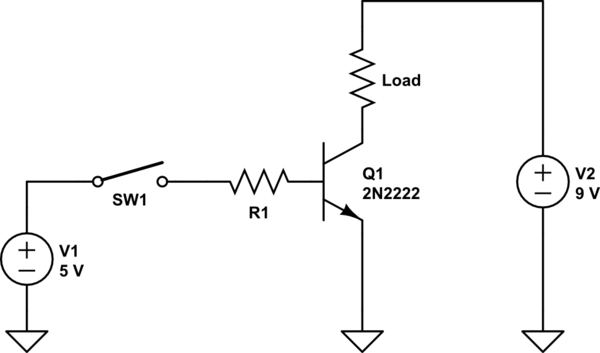
Since you're using a N-type device, you want to perform "low-side switching". The emitter is tied to ground, and the voltage is measured between the high supply and the collector.

schematic

simulate this circuit – Schematic created using CircuitLab

R1 should be sized so that enough current is allowed through to saturate the transistor without allowing VBE to cause the supply voltage to sag too much.

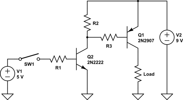
If you still want to perform high-side switching of a higher voltage then you should switch to a P-type device instead and put a N-type device in front of it to switch it.

schematic

simulate this circuit

\$\endgroup\$
3
  • \$\begingroup\$ Thank you Ignacio. I used Peters suggestion and am getting the correct reading in my multimeter now. Appreciate your help! \$\endgroup\$
    – Marko
    Commented Jan 1, 2014 at 0:54
  • 1
    \$\begingroup\$ Regarding the high side switch PNP configuration you show and the fact that the base is driven from an Arduino with either 0v or 5v, how do you expect this to work? I see a circuit that will never turn off, the Vbe will either be 4v or 9v. \$\endgroup\$
    – alexan_e
    Commented Jan 1, 2014 at 10:01
  • \$\begingroup\$ @alexan_e: You're right, I don't know what I was thinking. \$\endgroup\$ Commented Jan 2, 2014 at 23:38

Your Answer

By clicking “Post Your Answer”, you agree to our terms of service and acknowledge you have read our privacy policy.

Not the answer you're looking for? Browse other questions tagged or ask your own question.