0
\$\begingroup\$

I have a transistor which will be triggered by an arduino digital pin. When the transistor switch is closed, ~5 A is going to flow from the collector to the emitter. However, I was under the impression that both the base and the emitter need to be grounded at the same place. I'm worried about that kind of current going into the Arduino's ground, because I've heard it can't handle that much current. Is there a better way of doing this? Any advice is much appreciated.

Edit: I'm using a TIP3055 transistor and switching 12 VDC.

\$\endgroup\$
1
  • 1
    \$\begingroup\$ It's important to mention what transistor you're planning on using and what kind of load do you want to switch. Don't make us assume things! \$\endgroup\$
    – m.Alin
    Commented Sep 26, 2012 at 19:18

2 Answers 2

1
\$\begingroup\$

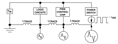
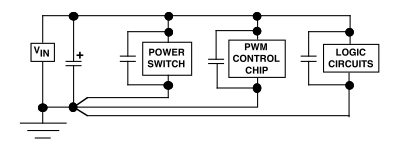
You have stumbled upon a very, very important issue. Take a look at two circuits with slightly different topologies:

enter image description hereenter image description here

The first circuit, as you can see, has the return lines branching out from a node that is close to a stable ground. In the second circuit, the currents returning from power circuits flow through the microcontroller's return line. The trace inductance and resistance will have a potentially significant voltage drop. A voltage across a "gnd" trace will cause your Arduino's power supply to be corrupted with unncecessary noise. Furthermore, the connectors that your arduino uses are rated up to 1A. The pcb traces pcb are even more prone to damage.

Connect your circuitry according to the upper image and your high current signals won't fry any traces on your Arduino.

\$\endgroup\$
9
  • 1
    \$\begingroup\$ PS. I don't know what are your going to use to power your circuits, but you definitely cannot draw 5A from the USB. I hope you're using a battery or a separate power supply. \$\endgroup\$ Commented Sep 26, 2012 at 19:10
  • \$\begingroup\$ Yeah, I have another power supply. \$\endgroup\$
    – Mason
    Commented Sep 26, 2012 at 19:17
  • \$\begingroup\$ Nice pictures. Where they're from? \$\endgroup\$
    – m.Alin
    Commented Sep 26, 2012 at 19:22
  • 1
    \$\begingroup\$ I think you can say that's exactly the essence of it. The point lies in what is the common return path for the currents. In practice, this means that it's better to use separate cables or traces for logic and power, and connect them together to the main GND in a place that is very close to the power supply. Your main power supply will be the Vin, your arduino will be the "Logic" and the transistor can be called a "power switch". \$\endgroup\$ Commented Sep 26, 2012 at 20:06
  • 1
    \$\begingroup\$ You are correct. Good luck! \$\endgroup\$ Commented Sep 27, 2012 at 6:24
1
\$\begingroup\$

You are confused as to how transistors work. You may want to ground the emitter if this is a low side switch, but you certainly don't want to ground the base. The base is the input signal to the transistor.

Another problem is that the base will likely require more current than a microcontroller digital output can source. You want to switch 5 A, which will require a reasonable "power transistor". Even being generous and saying you get one with a gain of 50 at 5 A, that still requires 100 mA base current. You could use another transistor in emitter follower configuration driving the power transistor, or perhaps use a FET. Knowing what the voltage will be on the switch when open is useful in deciding the best strategy.

Added:

Now that you say you only need to switch 12 V, a FET will be a better fit. At that low voltage, you can find FETs that can turn on well with only 5 V on the gate. That means they can be driven directly from a 5 V digital logic output. In fact, these are sometimes called "logic level" FETs. 5 A is pretty high, but you may be able to find a FET that can do that with 5 V gate drive (I haven't looked). If not, you can definitely get this by paralleling two FETs. Unlike bipolar transistors, MOSFETs can be paralleled since their D-S resistance goes up with temperature. I use the IRLML2502 a lot for these kind of low voltage but decent current switching applications. A single IRLML2502 can't handle the current, but two in parallel will be fine. However, I would first look to see if you can find one that can do the whole job.

I haven't looked up the TIP3055, but just from it's name I'm guessing its a 2N3055 variant. That is a high current power transistor, but also has very low gain. You may need as much as 500 mA base current to get 5 A collector current. Driving that from a digital output will take additional active parts. The FET solution will be much simpler and will dissipate less power. You can probably get away without a heat sink with the right FET or FETs.

\$\endgroup\$
4
  • \$\begingroup\$ So should I not be hooking up anything to the arduino's gnd pin? That seems unintuitive, but I may just be confused. \$\endgroup\$
    – Mason
    Commented Sep 26, 2012 at 19:07
  • 1
    \$\begingroup\$ @Mason: If this is a low side switch, then the emitter should be connected to the arduino's ground. \$\endgroup\$ Commented Sep 26, 2012 at 19:09
  • \$\begingroup\$ I'm sorry, can you explain exactly what you mean by a "low side switch"? \$\endgroup\$
    – Mason
    Commented Sep 26, 2012 at 19:17
  • \$\begingroup\$ Worth mentioning that he might require a protection diode if the load is inductive. \$\endgroup\$
    – m.Alin
    Commented Sep 26, 2012 at 20:07

Your Answer

By clicking “Post Your Answer”, you agree to our terms of service and acknowledge you have read our privacy policy.

Not the answer you're looking for? Browse other questions tagged or ask your own question.