I am planning to add an additional 12volt deep cycle battery to my APC UPS but I dont want to use the charging circuit built into the UPS. I think that if I throw in a Diode between the external battery and the UPS system it would accomplish my goal (and add an external charger). My question is about the rating of the diode that I should purchase. I am thinking that during a power failure, the load will be about 600watts. Would a 50V 5Amp diode be appropriate? What could I use that would be good for this applications? Thanks in advance for your replies, thoughts and suggestions.
-
\$\begingroup\$ The power equation is P=V*I , for 600W and an ideal efficiency of 100% the current for 12V would be 600W/12V=50A. In reality you need a considerably higher current plus headroom for surges. \$\endgroup\$– alexan_eCommented Jan 11, 2014 at 20:53
-
\$\begingroup\$ A relay MAY be an OK solution but at 60A they still cost some $ and need designing and my FET suggestion may be better overall. May need as little as a diode + resistor + FET to use. When charger is present Vin_charge drives FET gate. Resistor is gate pulldown to stop gate floating when no Vin_chg. \$\endgroup\$– Russell McMahon ♦Commented Jan 13, 2014 at 2:39
-
\$\begingroup\$ Hi Russell, Thank you for your replies and suggestions, the bigger problem for me is figure out the circuit needed. I am very good with the iron but not at all competent to pull together a design based on a FET. Would you be able to draw something for me that I can build and use for my project? \$\endgroup\$– user35420Commented Jan 15, 2014 at 0:35
3 Answers
I doubt this will work as I'd expect the inverter circuit expects the battery to be a very low impedance in both directions.
To size the diode you might take the output power that your UPS can provide and refactor that to the 12V battery. Assume some loss in transform, say 50%.
If your UPS is rated for 100 watts, then your battery will need to supply 150 watts, about 13A.
If your idea would work, the diode needs to be about 20A for a 100W output.
The diode will likely need a heat sink as it would be dissipating about 10 watts.
A diode will drop voltage causing the UPS to shut down sooner (IIRC APC Smart-UPS I have shuts down when the voltage drops to 10.5V under load).
600W/10.5V would be ~57A. You would need a diode rated for at least 60A, but probably should use a bigger one so that it drops less voltage. Read the datasheet of the diode and find one that can sustain 60A or higher current and has the lowest voltage drop at that current. For example, 400CNQ (2x400A) with both sides connected in parallel would drop about 0.25V (at 150C) to 0.4V (at 25C) and would dissipate about 57A*0.4V=22.8W, so it would need a big heatsink or a heatsink with a fan.
-
\$\begingroup\$ Schottky diodes offer lower voltage drop; finding a 60A one may be difficult but paralleling several may work. \$\endgroup\$– user16324Commented Jan 11, 2014 at 22:27
I_diode mex >= Power_UPS / V_UPS >= 50A
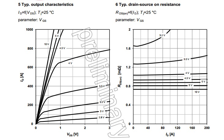
An ultra-low Rdson MOSFET used as a diode gives the best results.
A MOSFET can provide Rson of < 1 milliOhm at 50A.
V drop < 0.05V.
MOSFET loss < 2.5W at 50A.
As others have noted,
I diode operating
~=Power_ups / I operating diodes
~= 600 W / 12V- >= 50A.Even the best diodes are liable to have a voltage drop of tenths of a volt and probably > 0.5V at these currents at < 100C.
And diode cost will probably be $50+
MOSFETs with maximum Rdson at these currents of < 1 milliOhm max are available for under $10 each. A circuit is required to allow these to turn on and off as required but this is trivially simple.
Datasheet Infineon IPB009N03L {preliminary}
30V, 180A, < milliOhm Rdson.
Wow!

-
\$\begingroup\$ Thanks, I am thinking that I'll use a relay circuit which connects the battery to the USP when there is power loss this way I don't have to worry about anything else :-) \$\endgroup\$ Commented Jan 12, 2014 at 22:03
