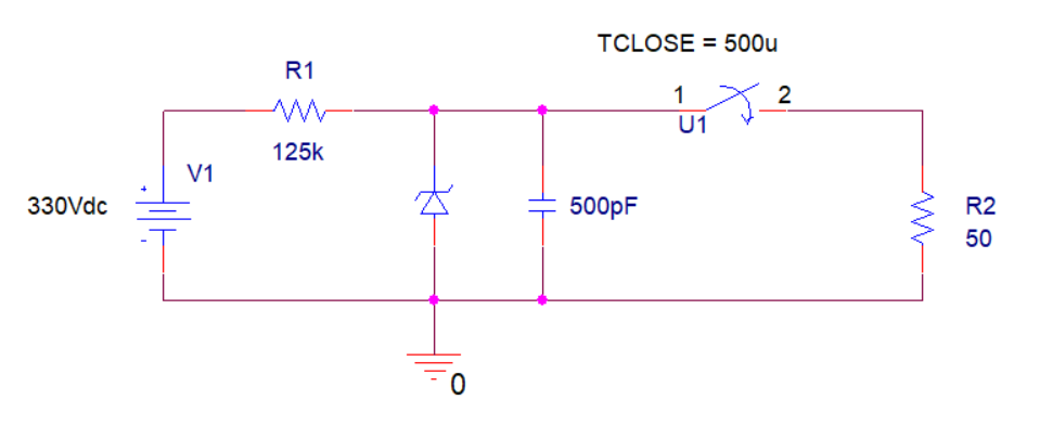
I'm testing a simple enough circuit on PSPICE. The zener has a BV = 220V, so the capacitor has a voltage of 220V until the switch closes.

- Using the time equation for voltage of a capacitor: Vc(t) = Vo * e^(-t/tau)
Vc(1ns) = 220V * e^(-1ns/50*500pF) = 211.37V
Vc(25ns) = 220V * e^(-25ns/50*500pF) = 80.93V
Vc(50ns) = 220V * e^(-50ns/50*500pF) = 29.77V
Vc(75ns) = 220V * e^(-50ns/50*500pF) = 10.95V
Vc(100ns) = 220V * e^(-50ns/50*500pF) = 4.02V
- Calculate dV/dt:
1ns --> dV/dt = (220V - 211.37V)/1ns = 8.63E9
25ns --> dV/dt = (220V - 80.93V)/25ns = 5.56628E9
50ns --> dV/dt = (220V - 29.77V)/50ns = 3.8046E9
75ns --> dV/dt = (220V - 10.95V)/75ns = 2.787E9
100ns --> dV/dt = (220V - 4.02V)/100ns = 2.1598E9
- And using the current equation for capacitors: Ic(t) = C*dV/dt
Ic(1ns) = 500pF*8.63E9 = 4.315A
Ic(25ns) = 500pF*5.56628E9 = 2.78A
Ic(50ns) = 500pF*3.8046E9 = 1.90A
Ic(75ns) = 500pF*2.787E9 = 1.3935A
Ic(100ns) = 500pF*2.1598E9 = 1.079A
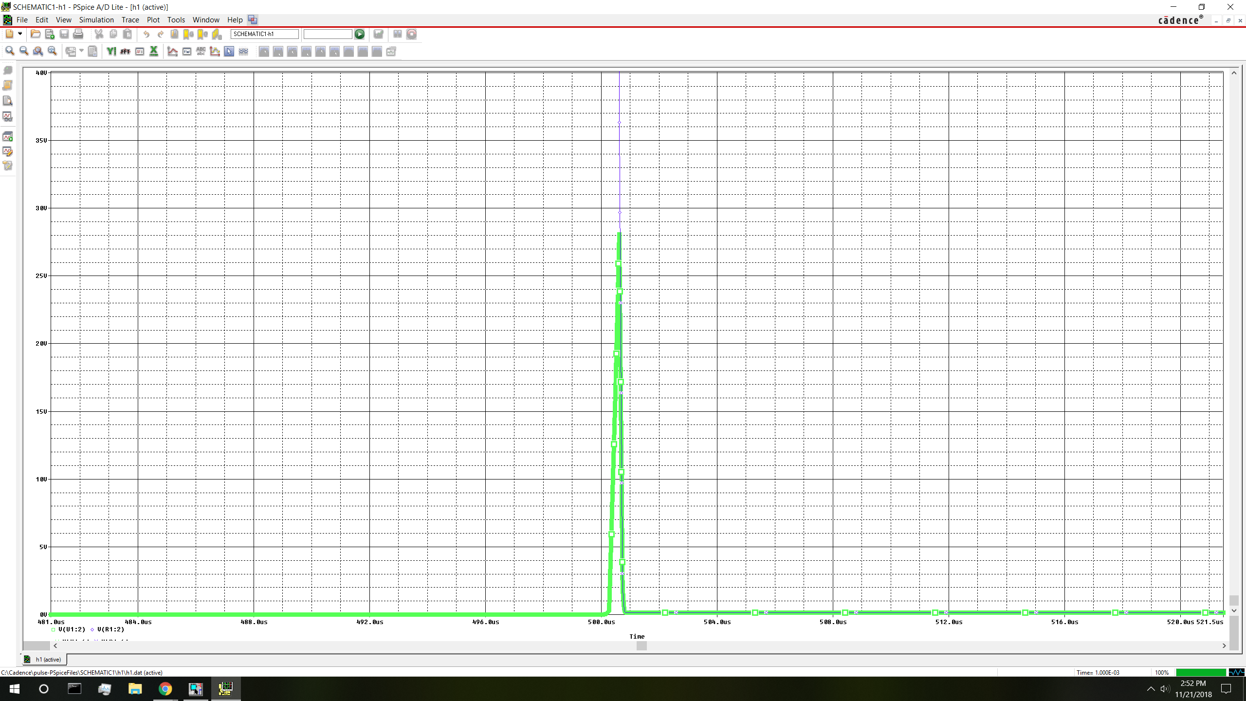
Seems great. Unfortunately, PSPICE disagrees.
The peak voltage node R2 reaches after the switch closes is only around 28V. It's clear to see that based on the topology this is just one big voltage divider. There shouldn't be any voltage at all on the top node after the switch closes because the overwhelming majority of voltage is dropped across R1. This doesn't explain why the capacitor releases such a wimpy peak in voltage though.
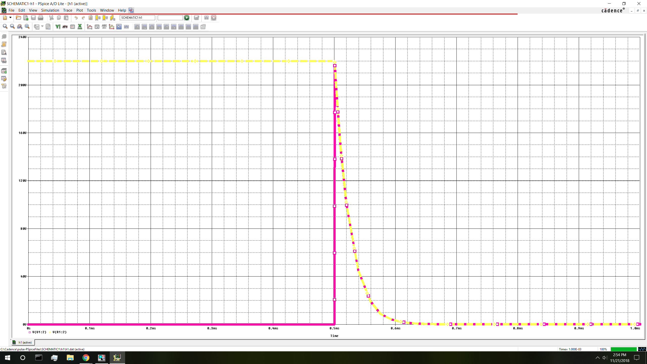
So I simply decide to test out 500nF, and poof! I get an output that I was expecting for the 500pF capacitor. But, I still don't understand why neither of these simulations discharges the capacitor within the expected time constant of 100ns. It should be almost completely discharged at 4tau.
Obviously PSPICE cannot be wrong. What am I missing here?


