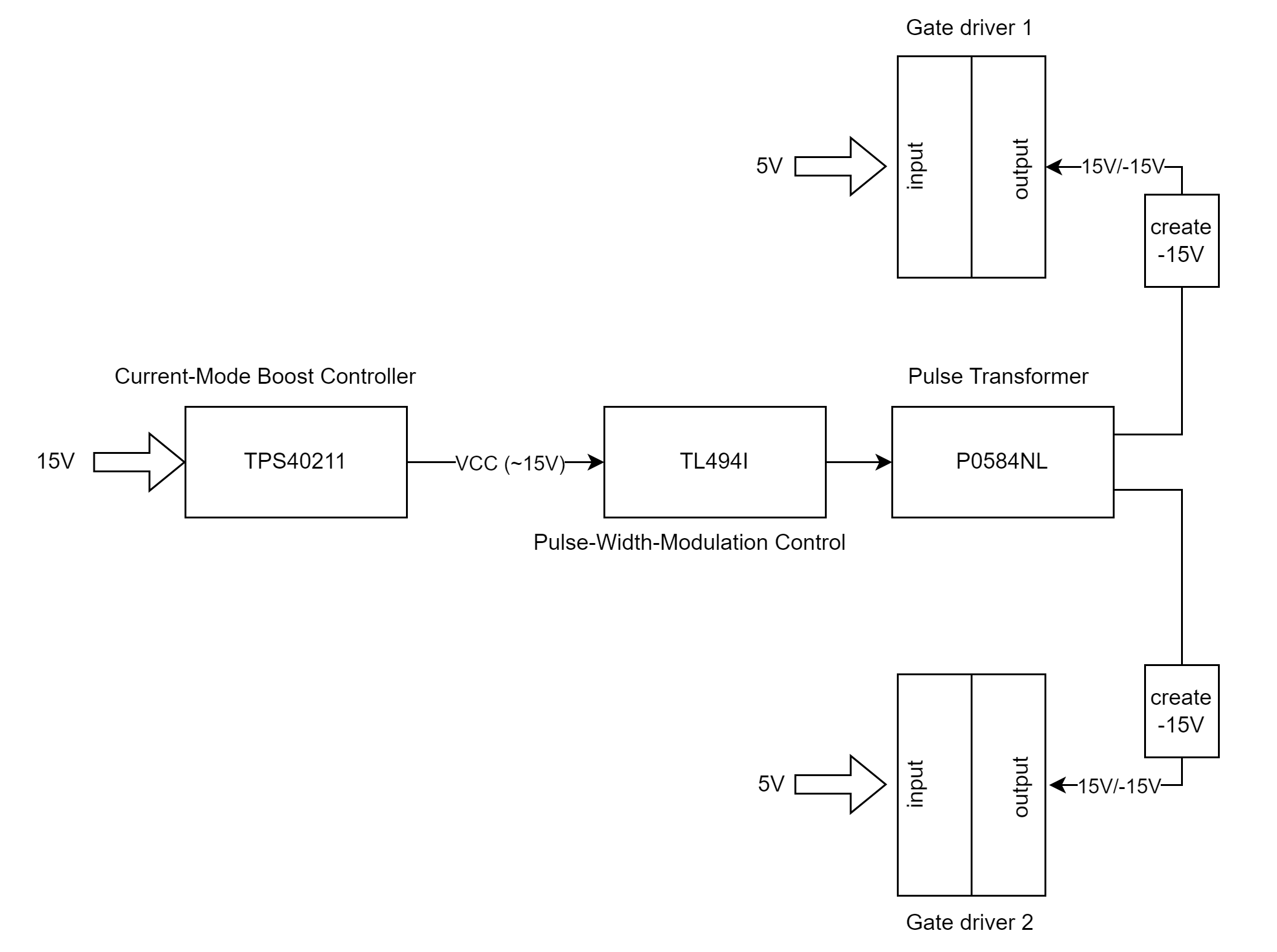
I have some questions concerning this schematic:
What is the topology used here? I am guessing flyback without feedback circuitry.
Why is the TPS40211 utilized here? Is it to provide more current? Rather than using the 15 V of the input, this chip is used to provide more current for the gate drivers to drive the IGBTs (which require +4 A). Am I right?
The transformer has two identical secondaries. Each one is used to drive the output of a gate driver, which requires a bi-bolar power supply. How can I use each secondary to provide both +15 V and -15 V?
There is a note in the gate driver transformer datasheet: "These gate drive transformers are meant to operate between 50 and 300 kHz with a 12 V, 45% bipolar waveform". Does that mean it can't operate at 15 V?
The circuits are basically the same as the typical recommendation in the datasheet but I couldn't figure out the connection between the two ICs.
The circuit goes something like this:


