Task: Design a ZCD for 230VAC to be interfaced to an atmega168, 5VDC.
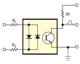
The pictured optocoupler is SFH620A-3. I have on hand 1/4W E24 resistors. I am extremely lazy and want to get away with as little soldering as possible (thank God the opto has only four leads).
Let's suppose the line voltage varies from V_{min} = 200VAC to V_{max} = 250VAC rms.
$$ P_{input resistors} = \frac{V_{max}^2}{R_1 + R_2}$$ $$ R_1 + R_2 \geq \frac{V_{max}^2}{P_{input resistors, max}} = \frac{250^2}{0.25+0.25} = 125Kohm$$
We select R1 = R2 = 68Kohm. $$ i_{in, min} = \frac{V_{min} - 1.65}{2 * R_1 *1.05} = \frac{198.35V}{142.8Kohm} = 1.39mA$$
From here on, using these or these calculations, we select 10Kohm or 15kohm for the output resistor.
Conclusion: minimum component count and price, borderline reliability, should work for a couple of years at least.
Would the schematic work? Would it be reliable for a couple of years of constant operation?
The output stage:
$$ i_C \geq i_{in, min} * CTR_{min} \approx 1.39 mA * 0.34 \approx 0.47mA $$
atmega168, page 302
$$ i_{leakage} \leq 1uA $$ $$ V_{IL} = 0.3 Vcc = 0.3 * 5V = 1.5V $$ $$ V_{IH} = 0.6 Vcc = 0.3 * 5V = 3V $$
If we strive to be below 1V for logic zero: $$ i_C * R_{output} = 1V $$ $$ R_{output} = 1V / 0.47mA = 2.13Kohm$$
We select 2.4Kohm.
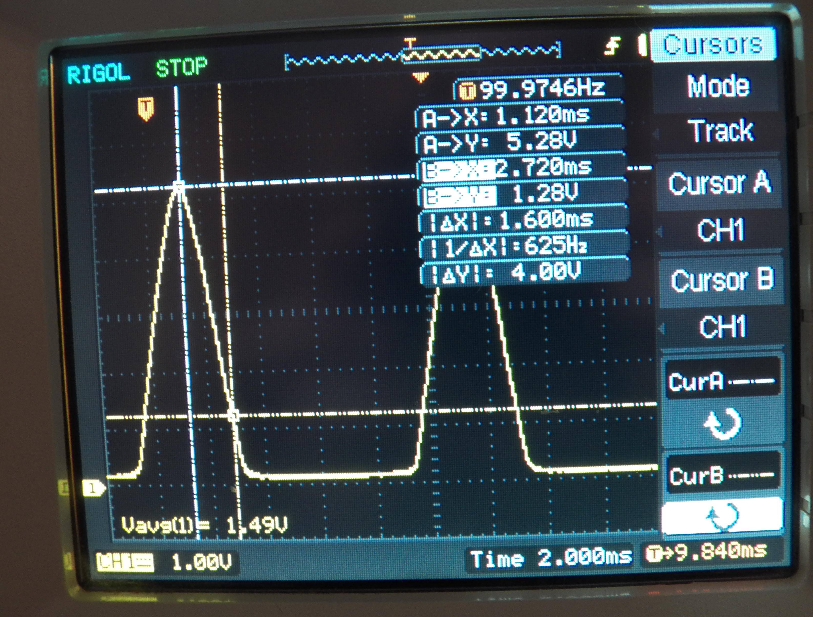
EDIT: implemented and tested. The input resistors get warm, but not hot.


check-designtag or something. Like we have a whole SE for code review. \$\endgroup\$