I have been recently working on a similar project. Here are the results of a zero cross detection experiment that I carried out:
(Before applying my results to your project, keep in mind that this experiment was carried out for 220V 50 Hz system and the system used 3.3V logic. Things will surely change for 110V 60V and 3.3V logic system.
Also, I felt no latency due to the load. I tested this circuit for loads in the range 20 watts - 250 watts. Last thing, you are using triacs which get pretty hot at a current of 2 amps (without heat sink). If you choose to control loads up to 1000 watts, make sure you are using a big heat sink for that application.
Aim of experiment: Implementing zero cross sensing of 220V 50 Hz ac line using opto-isolators.
Result of the experiment:
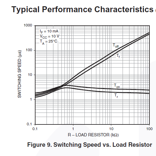
There is a lag between zero cross sense and actual zero cross and hence a certain delay must be used before switching on the triacs in order to maintain a stable operation.
Conclusion:
Zero cross sense circuit works flawlessly. However since logic high has a range, the sensing might be a little before the actual zero cross. This must be taken into account during coding for a robust performance. For the given circuit, a delay of minimum 2 ms will do the job.
Practically a minimum delay of 3ms can be given without any loss in dimming performance.
Similarly a max delay of 9 ms should be ensured.
Practically a max delay of 8.5ms can be given without loss in dimming performance.
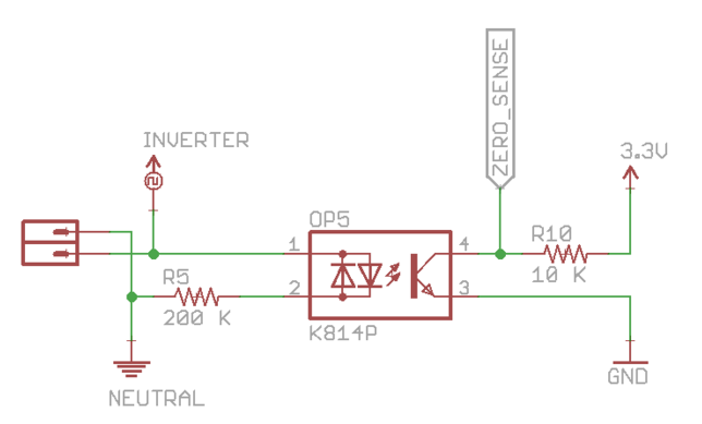
Circuit used for test:
Oscilloscope graph:
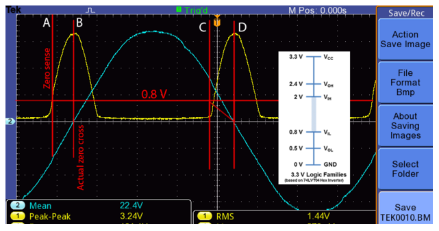
As seen here, 0.8 V is the max voltage which confirms a definite logic LOW signal. Any signal more than that might be recorded as HIGH.
Taking worst case scenario of HIGH detection at 0.8V itself, if the triac is turned on within 1.3 ms period of HIGH detection, it might lead to an unreliable behavior. If a minimum delay of 2 ms is assured in the code, it will ensure a robust dimming of the device without any flicker.
For max delay, considering the worst case scenario of zero detection at 2V, max delay can be 9.5ms. However to be on the safer side, a max delay of 9ms should be used.
Using oscilloscope with ac:
Ground probe of oscilloscope is connected to earth. So, make sure you NEVER connect that directly to Live by mistake. One hacky way around is to apply tape to the earth connector of oscilloscope power supply so that it gets disconnected from earth.
Also, if you are using 10x probe and you are not able to measure 220V (waveform is clipping on top and bottom), then if you add a 10 mega-ohms resistor in series with the probe, it will act as a cheap 20x probe and can be used to measure 220V without any issues. Don't forget to set the probe attenuation as 20x on the oscilloscope.



control-systembecause IMHO this topic is part of the science of System Identification, which is part of the Control Theory science. \$\endgroup\$