I have a circuit with a 220uF capacitor and a resistor is used to limit the inrush current
I stupidly fitted the wrong power rating resistor and (no surprise it failed) its taken me a while to realise my mistake. I believe the correct resistor is fine (it ran for a significant amount of time and is double the power) but I am a little bewildered as to how I calculate the rating and prove it theoretically
The resistors (I used two in parallel) fitted were 3R3 1.5W 2512 package
TE Connectivity CRGS2512J3R3
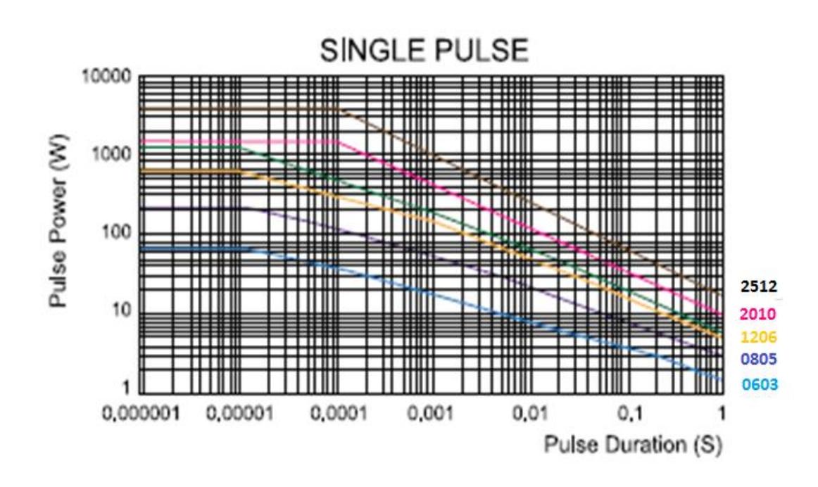
There is even a graph in the datasheet telling me the surge rating isnt adequate and I am interested in how they calculate these curves so I can apply the calcs to other resistors where they arent so helpful to provide a graph.
Here is the plot:
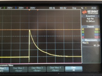
I measured the inrush with a scope (100VDC supply) and its a little over 40A, the theoretical max is over 60A but there is a reverse polarity protection diode and fuse and PCB trace and cap ESR reducing this.
That's the total inrush which passes through two resistors in parallel so approx 20A each resistor
As can be seen the surge has decreased to 50% of the peak after approximately 0.5ms so I believe I can treat this as a square wave with a width of 0.5ms as a decent approximation (like the EMC standards advise for TVS diodes etc)
There are app-notes online like
Vishays Pulse Load on SMD Resistors: At the Limit (again not enough repuation to add link)
I understand that periodic pulses require more derating than a single pulse (thats logical) at what point a single pulse becomes periodic is another topic as probably all electronics needs to be turned off at some point!
Using the calculation in vishays datasheet for periodic pulses with a 1 second period and using my inrush measurement data
P = (V^2/R)*ti/tp
V =100, R=3.3, ti = 0.0005, tp = 1
Gives me a value of 1.515W (absolute max) and I can see if applied surges more frequently then the power increases (which is what happened when the resistor failed)
Looking at the graph from the datasheet (isnt easy on the eye) but with 20.1A through the 3R3 resistor then thats a peak power of 1333W
The graph from the datasheet doesnt seem to agree for example derating for a 0.001 pulse time (for a convenient point to read off the values) the graph says approx 1kW max peak pulse power where as the calculation says that the average would be approx 3W which is double the rating of the resistor
I think I have spent too much time looking at this and simply need to go to bed and wake up fresh, I am confused if I am doing this right or do I just not have a clue!
I can calculate the energy into the capacitor but not sure what I would do with that, is the method right? is there a better way? Is this the way to do it when the manufacturer dont specify pulse/surge ratings?
Any advice is much appreciated


