ADDED THE CIRCUIT
Source Link

So, I want to make a High-Frequency Ferrite transformer that can convert my 150-volt peak Square wave into 100000 Volt Peak.

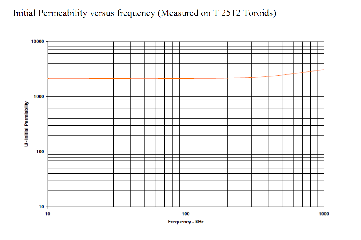
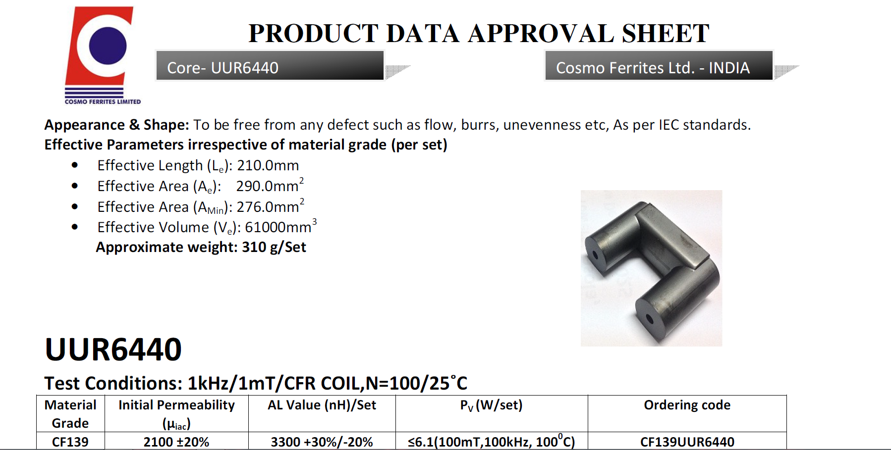
I am using UUR6440 Ferrite Core. Material is CF139

https://www.cosmoferrites.com/Downloads/Alnh/CF139.pdf.

enter image description here

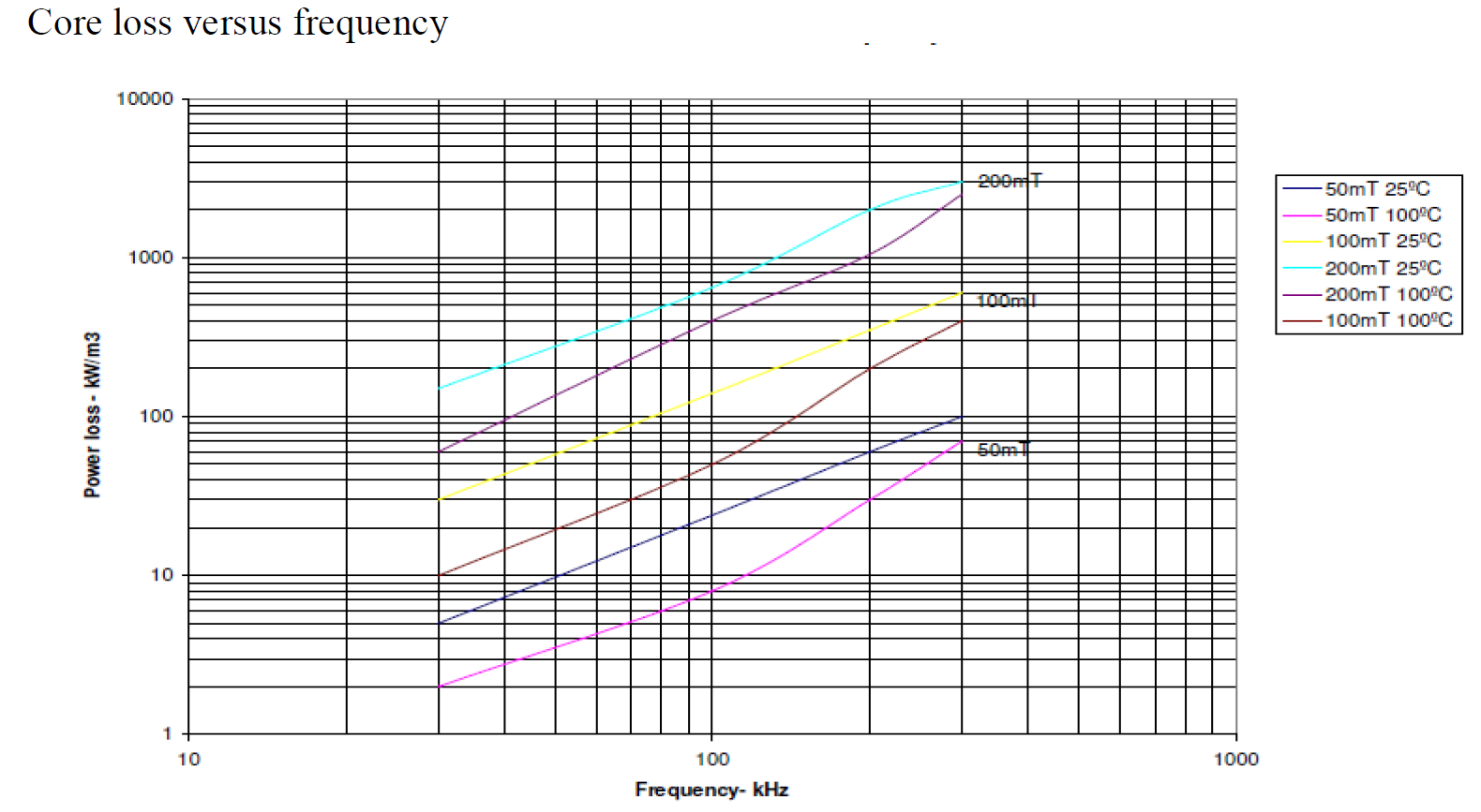
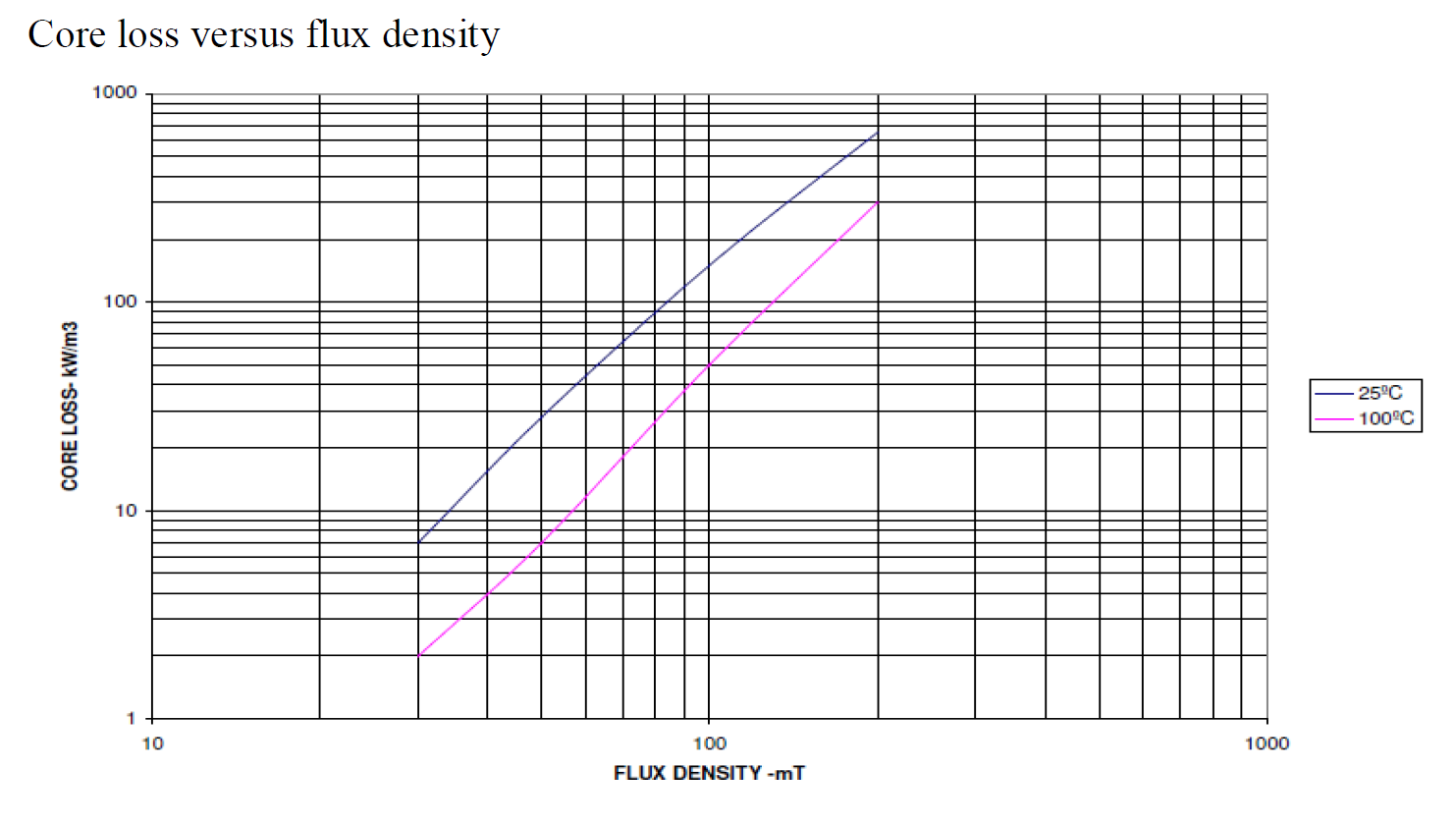
Below is the chart of the material. CORE LOSS VS FLUX DENSITY.

enter image description here My power supply setup is Half-Bridge topology for now. In the final design, I will use the H bridge. I have used 2* G4PC50UD Igbt to generate the Square wave.

enter image description here

For my design, I have used Bmax as 35mT, or 3500 gausses. I have calculated primary using this formula.(0.5 * Vin * 10^8)/ 4 * F * Bmax * Cross-section-Area). I have added 0.5 cause my design is Half Bridge. My switching Frequency is 50Khz. And my cross-section area is 2.9cm^2. So the result is 3.69 turn, so have used 4 turns in primary using 6mm square Wire. I need not more than 28mA in Secondary, so I have used 37AWG wire. And the secondary turn I have calculated using *(Vs/Vp)Np= 2666 Turns in secondary. But I have used 3000 turns in secondary.

Now the problem I am facing is while my secondary is at 0/NO loads,my Primary current is drawing 15-ampere peak at 40 volts RMS. When I am trying to give more voltage in the primary, the primary is drawing more current proportional to the primary voltage. Even when I am trying to generate an ARC in secondary the primary peak current is the remain the same. At 40 volt RMS my secondary should generate 4*666.66 = 26640 Volt. But the arc is only 1cm Long. My power is supply can provide up to 3KW.

  1. So can I generate 100000 Volt at 28 milliamps using my current setup?

  2. Why my ferrite transformer drawing 15amp peak at 40-volt RMS at NO loads ?, I mean when the secondary is not generating any ARC or the secondary wires are not even close? I have measured the secondary wire resistance. The resistance is 535 ohms.

  3. If my calculation is all wrong what you suggest I should be doing to generate 100000 Volts at 28 milliamps?

schematic

simulate this circuit – Schematic created using CircuitLab

So, I want to make a High-Frequency Ferrite transformer that can convert my 150-volt peak Square wave into 100000 Volt Peak.

I am using UUR6440 Ferrite Core. Material is CF139

https://www.cosmoferrites.com/Downloads/Alnh/CF139.pdf.

enter image description here

Below is the chart of the material. CORE LOSS VS FLUX DENSITY.

enter image description here My power supply setup is Half-Bridge topology for now. In the final design, I will use the H bridge. I have used 2* G4PC50UD Igbt to generate the Square wave.

enter image description here

For my design, I have used Bmax as 35mT, or 3500 gausses. I have calculated primary using this formula.(0.5 * Vin * 10^8)/ 4 * F * Bmax * Cross-section-Area). I have added 0.5 cause my design is Half Bridge. My switching Frequency is 50Khz. And my cross-section area is 2.9cm^2. So the result is 3.69 turn, so have used 4 turns in primary using 6mm square Wire. I need not more than 28mA in Secondary, so I have used 37AWG wire. And the secondary turn I have calculated using *(Vs/Vp)Np= 2666 Turns in secondary. But I have used 3000 turns in secondary.

Now the problem I am facing is while my secondary is at 0/NO loads,my Primary current is drawing 15-ampere peak at 40 volts RMS. When I am trying to give more voltage in the primary, the primary is drawing more current proportional to the primary voltage. Even when I am trying to generate an ARC in secondary the primary peak current is the remain the same. At 40 volt RMS my secondary should generate 4*666.66 = 26640 Volt. But the arc is only 1cm Long. My power is supply can provide up to 3KW.

  1. So can I generate 100000 Volt at 28 milliamps using my current setup?

  2. Why my ferrite transformer drawing 15amp peak at 40-volt RMS at NO loads ?, I mean when the secondary is not generating any ARC or the secondary wires are not even close? I have measured the secondary wire resistance. The resistance is 535 ohms.

  3. If my calculation is all wrong what you suggest I should be doing to generate 100000 Volts at 28 milliamps?

schematic

simulate this circuit – Schematic created using CircuitLab
Source Link

Ferrite core StepUP Transformer Design

So, I want to make a High-Frequency Ferrite transformer that can convert my 150-volt peak Square wave into 100000 Volt Peak.

I am using UUR6440 Ferrite Core. Material is CF139

https://www.cosmoferrites.com/Downloads/Alnh/CF139.pdf.

enter image description here

Below is the chart of the material. CORE LOSS VS FLUX DENSITY.

enter image description here My power supply setup is Half-Bridge topology for now. In the final design, I will use the H bridge. I have used 2* G4PC50UD Igbt to generate the Square wave.

enter image description here

For my design, I have used Bmax as 35mT, or 3500 gausses. I have calculated primary using this formula.(0.5 * Vin * 10^8)/ 4 * F * Bmax * Cross-section-Area). I have added 0.5 cause my design is Half Bridge. My switching Frequency is 50Khz. And my cross-section area is 2.9cm^2. So the result is 3.69 turn, so have used 4 turns in primary using 6mm square Wire. I need not more than 28mA in Secondary, so I have used 37AWG wire. And the secondary turn I have calculated using *(Vs/Vp)Np= 2666 Turns in secondary. But I have used 3000 turns in secondary.

Now the problem I am facing is while my secondary is at 0/NO loads,my Primary current is drawing 15-ampere peak at 40 volts RMS. When I am trying to give more voltage in the primary, the primary is drawing more current proportional to the primary voltage. Even when I am trying to generate an ARC in secondary the primary peak current is the remain the same. At 40 volt RMS my secondary should generate 4*666.66 = 26640 Volt. But the arc is only 1cm Long. My power is supply can provide up to 3KW.

  1. So can I generate 100000 Volt at 28 milliamps using my current setup?

  2. Why my ferrite transformer drawing 15amp peak at 40-volt RMS at NO loads ?, I mean when the secondary is not generating any ARC or the secondary wires are not even close? I have measured the secondary wire resistance. The resistance is 535 ohms.

  3. If my calculation is all wrong what you suggest I should be doing to generate 100000 Volts at 28 milliamps?