deleted 86 characters in body
Source Link
Voltage Spike
  • 88.8k
  • 49
  • 90
  • 234

I have this question that has been haunting me for quite a while now. I know for a fact that to take into account frequency-dependent behavior in time domain simulation, equivalent electrical networks that reproduce the same frequency behavior are used, as it happens, an RL ladder circuit (Cauer circuit) as the one seen below are implemented:

enter image description here

It is always a matter of fitting the module of the impedance and never the phase. Since a frequency-dependent resistance has a zero phase no matter the frequency, how do you guys approach the fact that an equivalent passive circuit reproducing the same behavior (R(f)) -might(*)- have an additional phase to it and it has never been addressed(**) in previous research work. 

Also, I know this is more a mathematical question than physical, but what would you guys suggest as a technique when it comes to computing the values of the parameters R_i L_i that will eventually give a network that has the same frequency behavior as R(f) (or ultimately L(f))?

(*) It eventually does have a non-null phase since we have inductances in the equivalent circuit... (**) Or I still haven't come across it...

Thanks in advance :)

I have this question that has been haunting me for quite a while now. I know for a fact that to take into account frequency-dependent behavior in time domain simulation, equivalent electrical networks that reproduce the same frequency behavior are used, as it happens, an RL ladder circuit (Cauer circuit) as the one seen below are implemented:

enter image description here

It is always a matter of fitting the module of the impedance and never the phase. Since a frequency-dependent resistance has a zero phase no matter the frequency, how do you guys approach the fact that an equivalent passive circuit reproducing the same behavior (R(f)) -might(*)- have an additional phase to it and it has never been addressed(**) in previous research work. Also, I know this is more a mathematical question than physical, but what would you guys suggest as a technique when it comes to computing the values of the parameters R_i L_i that will eventually give a network that has the same frequency behavior as R(f) (or ultimately L(f))?

(*) It eventually does have a non-null phase since we have inductances in the equivalent circuit... (**) Or I still haven't come across it...

Thanks in advance :)
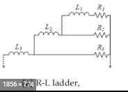
I know for a fact that to take into account frequency-dependent behavior in time domain simulation, equivalent electrical networks that reproduce the same frequency behavior are used, as it happens, an RL ladder circuit (Cauer circuit) as the one seen below are implemented:

enter image description here

It is always a matter of fitting the module of the impedance and never the phase. Since a frequency-dependent resistance has a zero phase no matter the frequency, how do you guys approach the fact that an equivalent passive circuit reproducing the same behavior (R(f)) -might(*)- have an additional phase to it and it has never been addressed(**) in previous research work. 

Also, I know this is more a mathematical question than physical, but what would you guys suggest as a technique when it comes to computing the values of the parameters R_i L_i that will eventually give a network that has the same frequency behavior as R(f) (or ultimately L(f))?

(*) It eventually does have a non-null phase since we have inductances in the equivalent circuit... (**) Or I still haven't come across it...

Source Link
Wallflower
  • 459
  • 4
  • 15

Frequency-dependent behavior of a resistor in time domain simulation

I have this question that has been haunting me for quite a while now. I know for a fact that to take into account frequency-dependent behavior in time domain simulation, equivalent electrical networks that reproduce the same frequency behavior are used, as it happens, an RL ladder circuit (Cauer circuit) as the one seen below are implemented:

enter image description here

It is always a matter of fitting the module of the impedance and never the phase. Since a frequency-dependent resistance has a zero phase no matter the frequency, how do you guys approach the fact that an equivalent passive circuit reproducing the same behavior (R(f)) -might(*)- have an additional phase to it and it has never been addressed(**) in previous research work. Also, I know this is more a mathematical question than physical, but what would you guys suggest as a technique when it comes to computing the values of the parameters R_i L_i that will eventually give a network that has the same frequency behavior as R(f) (or ultimately L(f))?

(*) It eventually does have a non-null phase since we have inductances in the equivalent circuit... (**) Or I still haven't come across it...

Thanks in advance :)