1
\$\begingroup\$

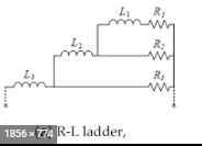
I know for a fact that to take into account frequency-dependent behavior in time domain simulation, equivalent electrical networks that reproduce the same frequency behavior are used, as it happens, an RL ladder circuit (Cauer circuit) as the one seen below are implemented:

enter image description here

It is always a matter of fitting the module of the impedance and never the phase. Since a frequency-dependent resistance has a zero phase no matter the frequency, how do you guys approach the fact that an equivalent passive circuit reproducing the same behavior (R(f)) -might(*)- have an additional phase to it and it has never been addressed(**) in previous research work.

Also, I know this is more a mathematical question than physical, but what would you guys suggest as a technique when it comes to computing the values of the parameters R_i L_i that will eventually give a network that has the same frequency behavior as R(f) (or ultimately L(f))?

(*) It eventually does have a non-null phase since we have inductances in the equivalent circuit... (**) Or I still haven't come across it...

\$\endgroup\$
12
  • \$\begingroup\$ I'm curious what your application is where you need such a high fidelity RLC model for a resistor, but you can still use a lumped-circuit model... \$\endgroup\$
    – W5VO
    Commented Jun 21, 2021 at 19:47
  • \$\begingroup\$ @W5VO I want to take into account the HF resistive phenomena, and I am inspired by this scientific paper ieeexplore.ieee.org/abstract/document/1644906. What about a lumped-circuit model how can I deduce it? \$\endgroup\$
    – Wallflower
    Commented Jun 21, 2021 at 20:05
  • \$\begingroup\$ @Wallflower What is your highest frequency that you need to simulate? \$\endgroup\$
    – Voltage Spike
    Commented Jun 21, 2021 at 20:27
  • \$\begingroup\$ @VoltageSpike From 50Hz to 500Khz \$\endgroup\$
    – Wallflower
    Commented Jun 21, 2021 at 20:40
  • 1
    \$\begingroup\$ Wherever a "frequency dependent resistor" comes up you'll see that it's actually expressed as a complex notation, with both real and imaginary parts. Therefore when you say that an R(f) has zero phase, you have a clash: either you have a resistance, which has no dependency on frequency, or an impedance, which has. You'll have to take a small grain of salt and consider that the naming seems to have been established, but they are impedances, therefore there is phase shift. \$\endgroup\$ Commented Jun 21, 2021 at 21:43

2 Answers 2

1
\$\begingroup\$

Your doubts are well founded. A frequency-varying pure resistance is not a physical thing. As the real part of an impedance changes with frequency, the imaginary part of the impedance is constrained to vary in a particular way. This is due to causality. (look up kramer-kroning relations) So, you can't build a circuit that that varies resistance with frequency without some phase shift in it. However, the constraints concern DC to Daylight, and if you are only interested in a limited frequency range, you can get close to a pure real impedance over that frequency range. (easier in low bandwidths, harder in high bandwidth cases).

But... you want a time domain simulation... which means you do want to get something that works over all frequencies. (high frequencies are the edges of your response, low frequencies are the flat places in your response.) I would guess that the equivalent circuits of the people modeling dielectric losses and such are "close enough" for their needs.

\$\endgroup\$
5
  • \$\begingroup\$ Thank u for your response. I am familiar with Kramer-Kroning relations and it did not cross my mind at all to view the problem from that angle. Thanks again for your enlightenment. As for the model of dielectric losses, a parallel RC circuit is the one generally used where C represents the stored electric energy and R the dielectric losses, but I really do not know what's the link with a frequency-dependent resistance? \$\endgroup\$
    – Wallflower
    Commented Jun 21, 2021 at 22:04
  • \$\begingroup\$ You showed the example with L-R networks for skin effect. I mentioned dielectric losses because that is the other frequency dependent loss in cable modeling, as in the article you referenced. \$\endgroup\$
    – user69795
    Commented Jun 21, 2021 at 23:32
  • \$\begingroup\$ Well actually for the frequency-dependent behavior of dielectric losses, an RC ladder is used to account for their frequency behavior, so I guess if I figure out how to compute the values of R_i L_i of the RL ladder that will reproduce the same behavior of skin & proximity effects over my frequency range of interest, I'll do the same for dielectric losses \$\endgroup\$
    – Wallflower
    Commented Jun 22, 2021 at 6:59
  • \$\begingroup\$ what would you suggest please as a way of computing the values of R_i L_i that will reproduce the same frequency dependent behavior as that of R(f)? \$\endgroup\$
    – Wallflower
    Commented Jun 22, 2021 at 8:54
  • 1
    \$\begingroup\$ Hi, Wallflower: I used to know much more about this than I now remember. There have been papers written on the theory of doing this. I believe, though, that the most practical and successful way is simply to start with the RL or RC circuit configuration and use circuit analysis based numerical optimization to fit the response to your desired curves. Some circuit analysis programs come with built in optimizers. These days brute force computing often beats theory. \$\endgroup\$
    – user69795
    Commented Jun 22, 2021 at 23:17
1
\$\begingroup\$

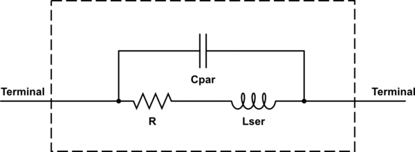
A lumped element model will be fine up to the GHz range, in the Tera-Hz range that is where things start to break down because materials start to behave different.

So if you plug in this model, R would be the resistance of the resistor. L and C can be estimated or measured.

L is from the leads and will be really small, in the nH range for most SMT parts. You can calculate if you know the material of the leads and the general shape, you can then calculate the resistance.

C is from the spacing of the conductors of the leads, and is usually in the pF range for many parts. You can get an estimate by using a parallel plate capacitor model for many resistors but it really depends on the geometry .

Most resistors won't have a frequent cutoff until the GHz range so I wouldn't even worry about using a more refined model unless you are working in that range.

schematic

simulate this circuit – Schematic created using CircuitLab

\$\endgroup\$
3
  • \$\begingroup\$ So it's more of the fitting of the function R(f) to a similar circuit right? \$\endgroup\$
    – Wallflower
    Commented Jun 21, 2021 at 22:05
  • 1
    \$\begingroup\$ Yeah, you can do that too, since it's easy to measure R and that doesn't change with frequency (maybe a bit in GHz range but not in MHz), you could fit L and C. L and C are usually very small so it would be hard to measure them directly, and usually estimating them is much easier if you don't need exact results. \$\endgroup\$
    – Voltage Spike
    Commented Jun 21, 2021 at 22:11
  • \$\begingroup\$ Thank you so much for the clarification :) \$\endgroup\$
    – Wallflower
    Commented Jun 22, 2021 at 7:15

Your Answer

By clicking “Post Your Answer”, you agree to our terms of service and acknowledge you have read our privacy policy.

Not the answer you're looking for? Browse other questions tagged or ask your own question.