added 40 characters in body
Source Link
Hasman404
  • 757
  • 6
  • 21

I would like to implement the following logic:

enter image description here

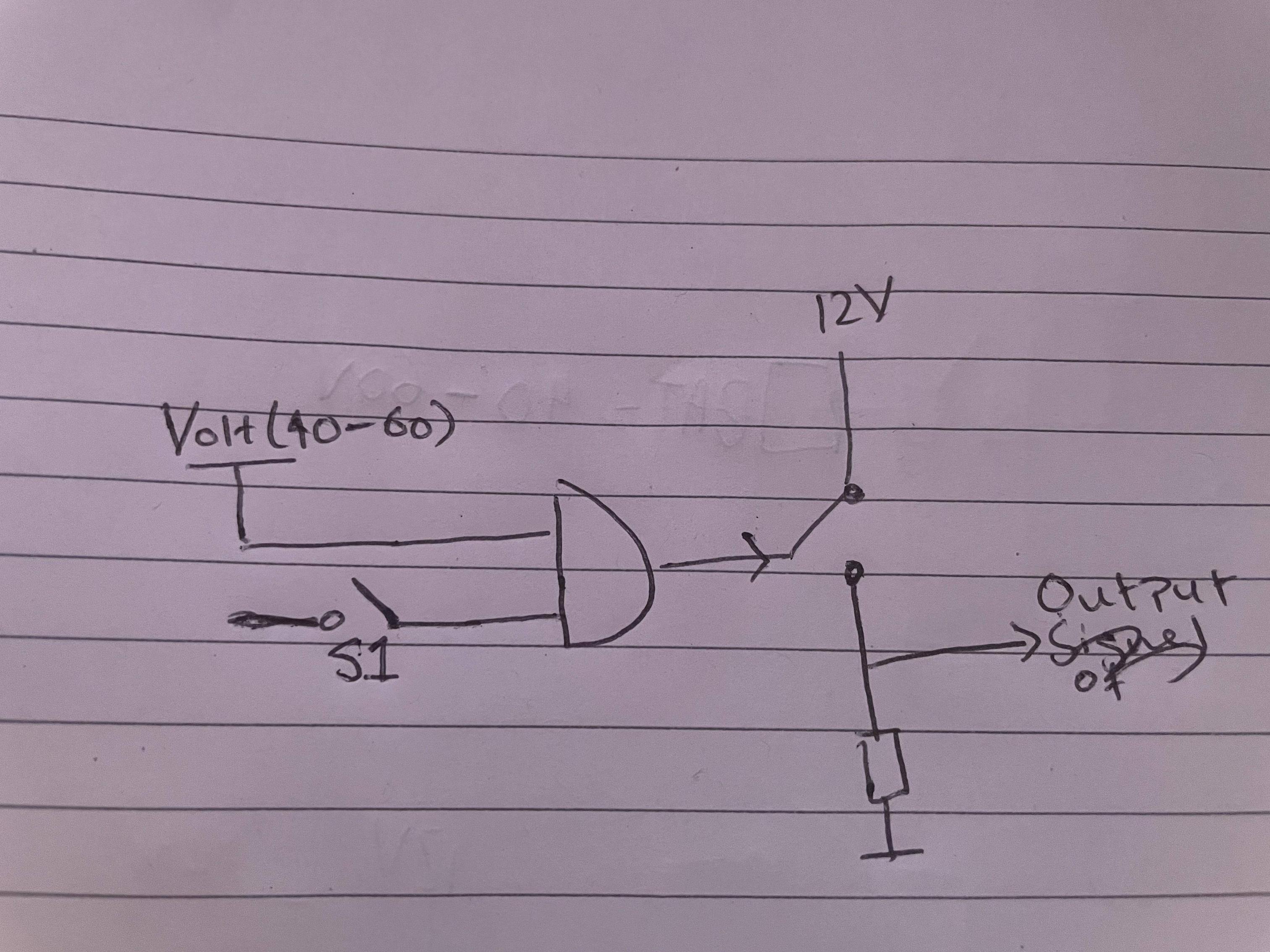
Whilst the switch S1 is pressed AND there is a voltage on VOLT (this would range from 40-60V) then the output switch would be closed and output would be at 12V. Otherwise the output is pulled to ground. I have drawn the AND gate purely to explain the logic. S1 is floating as it could be tied to ground or anything else that may be more suitable.

What would be a good way of implementing this? I considered using a pnp bjt but the variation on Volt would have made it fairly tricky to implement.

The output signal for a logic high must be between 11-13V. Does not have to be 12V. It just so happens that i have access to a 12V line.

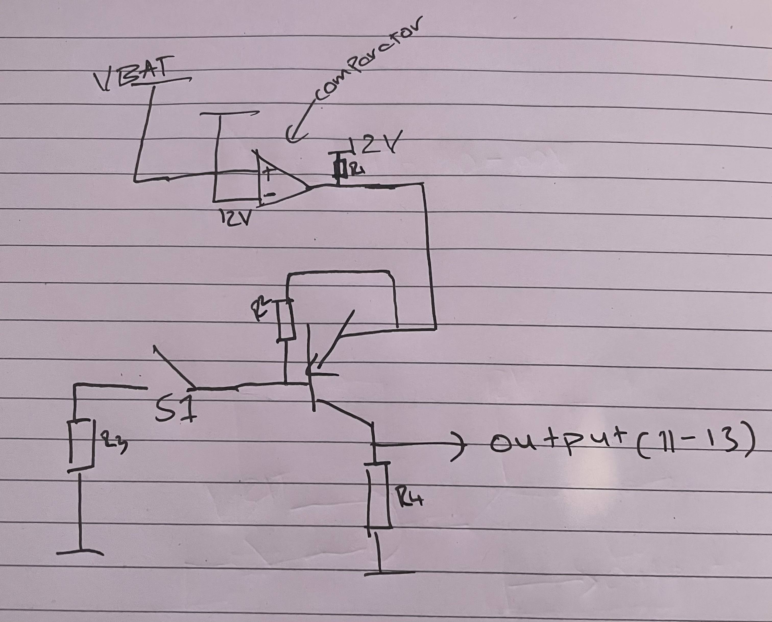
Would something like the following work (Apologies but VBAT here is VOLT(40-60V)?:

enter image description here

I would like to implement the following logic:

enter image description here

Whilst the switch S1 is pressed AND there is a voltage on VOLT (this would range from 40-60V) then the output switch would be closed and output would be at 12V. Otherwise the output is pulled to ground. I have drawn the AND gate purely to explain the logic. S1 is floating as it could be tied to ground or anything else that may be more suitable.

What would be a good way of implementing this? I considered using a pnp bjt but the variation on Volt would have made it fairly tricky to implement.

The output signal for a logic high must be between 11-13V. Does not have to be 12V. It just so happens that i have access to a 12V line.

Would something like the following work ?:

enter image description here

I would like to implement the following logic:

enter image description here

Whilst the switch S1 is pressed AND there is a voltage on VOLT (this would range from 40-60V) then the output switch would be closed and output would be at 12V. Otherwise the output is pulled to ground. I have drawn the AND gate purely to explain the logic. S1 is floating as it could be tied to ground or anything else that may be more suitable.

What would be a good way of implementing this? I considered using a pnp bjt but the variation on Volt would have made it fairly tricky to implement.

The output signal for a logic high must be between 11-13V. Does not have to be 12V. It just so happens that i have access to a 12V line.

Would something like the following work (Apologies but VBAT here is VOLT(40-60V)?:
enter image description here

Included a circuit option
Source Link
Hasman404
  • 757
  • 6
  • 21

I would like to implement the following logic:

enter image description here

Whilst the switch S1 is pressed AND there is a voltage on VOLT (this would range from 40-60V) then the output switch would be closed and output would be at 12V. Otherwise the output is pulled to ground. I have drawn the AND gate purely to explain the logic. S1 is floating as it could be tied to ground or anything else that may be more suitable.

What would be a good way of implementing this? I considered using a pnp bjt but the variation on Volt would have made it fairly tricky to implement.

The output signal for a logic high must be between 11-13V. Does not have to be 12V. It just so happens that i have access to a 12V line.

Would something like the following work ?:

enter image description here

I would like to implement the following logic:

enter image description here

Whilst the switch S1 is pressed AND there is a voltage on VOLT (this would range from 40-60V) then the output switch would be closed and output would be at 12V. Otherwise the output is pulled to ground. I have drawn the AND gate purely to explain the logic. S1 is floating as it could be tied to ground or anything else that may be more suitable.

What would be a good way of implementing this? I considered using a pnp bjt but the variation on Volt would have made it fairly tricky to implement.

The output signal for a logic high must be between 11-13V. Does not have to be 12V. It just so happens that i have access to a 12V line.

Would something like the following work ?:

enter image description here

Source Link
Hasman404
  • 757
  • 6
  • 21

Best way to design a circuit for the following AND logic

I would like to implement the following logic:

enter image description here

Whilst the switch S1 is pressed AND there is a voltage on VOLT (this would range from 40-60V) then the output switch would be closed and output would be at 12V. Otherwise the output is pulled to ground. I have drawn the AND gate purely to explain the logic. S1 is floating as it could be tied to ground or anything else that may be more suitable.

What would be a good way of implementing this? I considered using a pnp bjt but the variation on Volt would have made it fairly tricky to implement.

The output signal for a logic high must be between 11-13V. Does not have to be 12V. It just so happens that i have access to a 12V line.