0
\$\begingroup\$

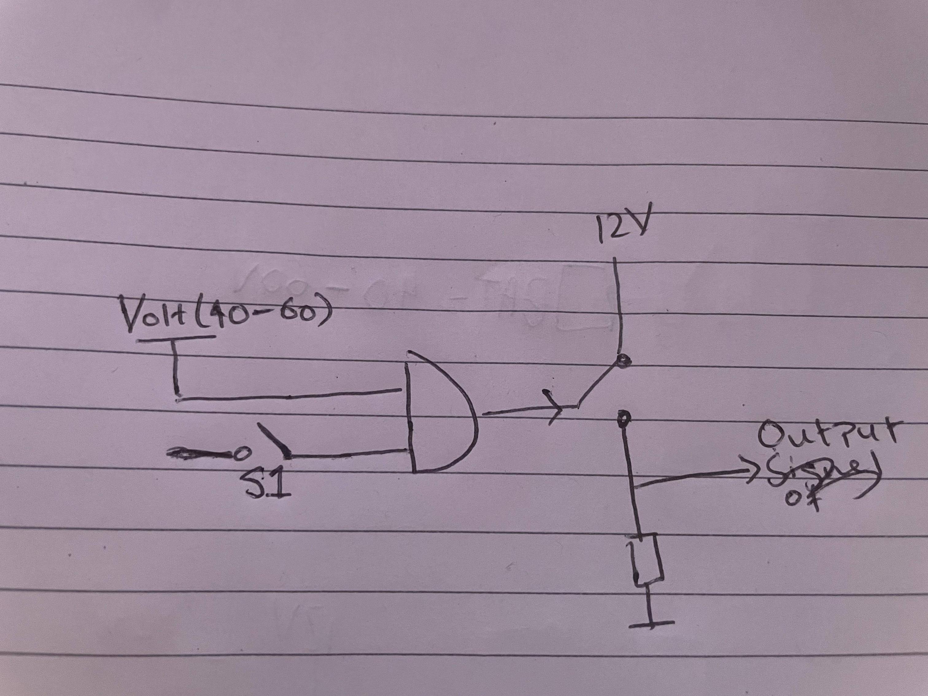
I would like to implement the following logic:

enter image description here

Whilst the switch S1 is pressed AND there is a voltage on VOLT (this would range from 40-60V) then the output switch would be closed and output would be at 12V. Otherwise the output is pulled to ground. I have drawn the AND gate purely to explain the logic. S1 is floating as it could be tied to ground or anything else that may be more suitable.

What would be a good way of implementing this? I considered using a pnp bjt but the variation on Volt would have made it fairly tricky to implement.

The output signal for a logic high must be between 11-13V. Does not have to be 12V. It just so happens that i have access to a 12V line.

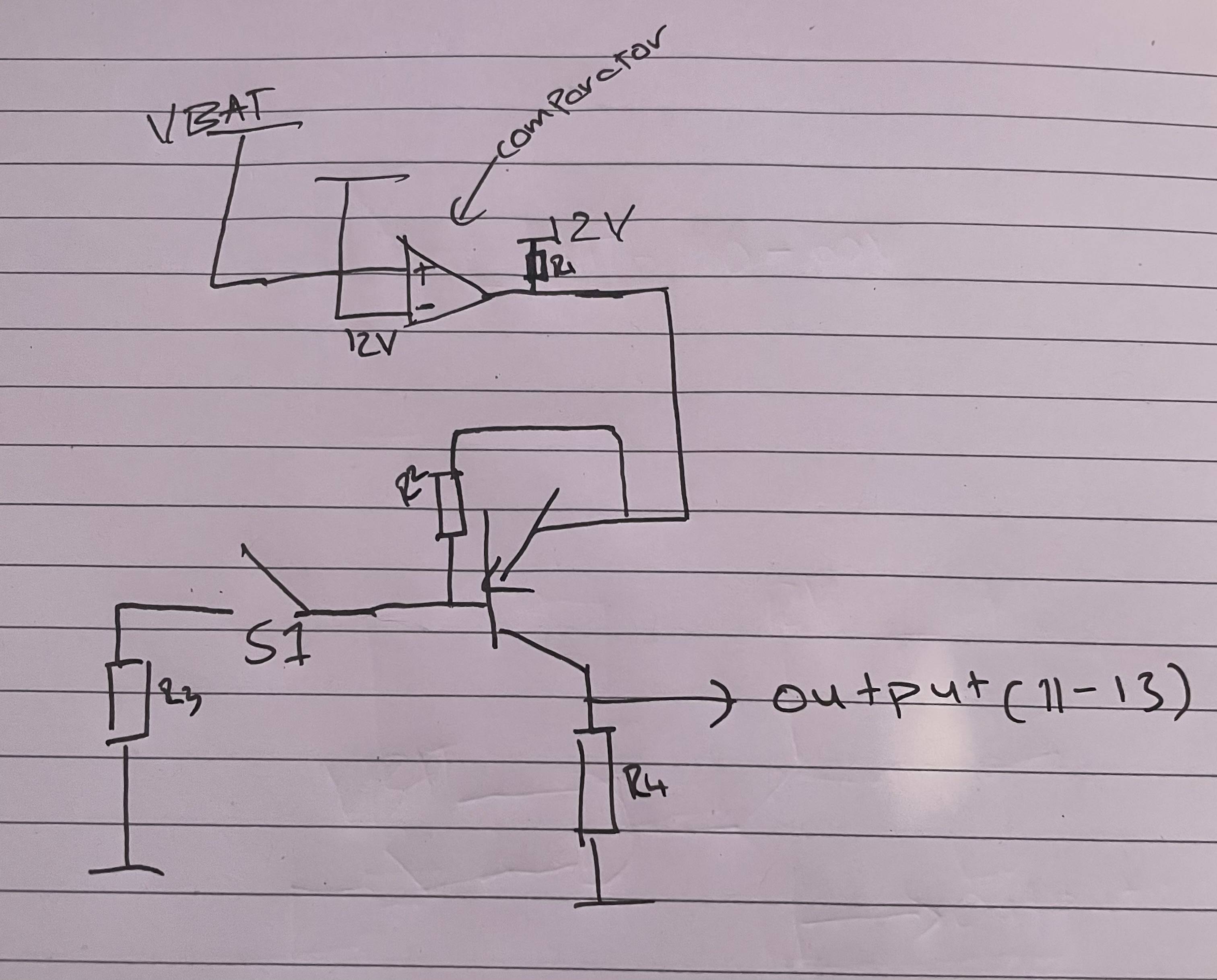
Would something like the following work (Apologies but VBAT here is VOLT(40-60V)?:

enter image description here

\$\endgroup\$
4
  • \$\begingroup\$ What if the voltage is 39 volts? <-- what do you want to happen? What happens if it's 39.999 volts or over 60 volts? You can attach 12 volts to the output of an op-amp. What is VBAT? Your 2nd picture appears to show the threshold being at 12 volts rather than 40 volts. Why can't you put the switch in series with the comparator output and get rid of the PNP transistor? \$\endgroup\$
    – Andy aka
    Commented Oct 24, 2022 at 19:56
  • \$\begingroup\$ No need for the pnp. Wasn't thinking straight. switch in series makes sense. I suppose the voltage source itself ranges from 40-60V. It would make sense for the threshold to be no more than 25% lower so say 30V). So yes that circuit is completely wrong. \$\endgroup\$
    – Hasman404
    Commented Oct 24, 2022 at 20:16
  • \$\begingroup\$ what's the output current? \$\endgroup\$ Commented Oct 24, 2022 at 21:06
  • \$\begingroup\$ How much current can you take from the 40-to-60-volts source? How much current does the output need to provide? -- Can't you simply use an appropriate relay? \$\endgroup\$ Commented Oct 25, 2022 at 6:02

3 Answers 3

1
\$\begingroup\$

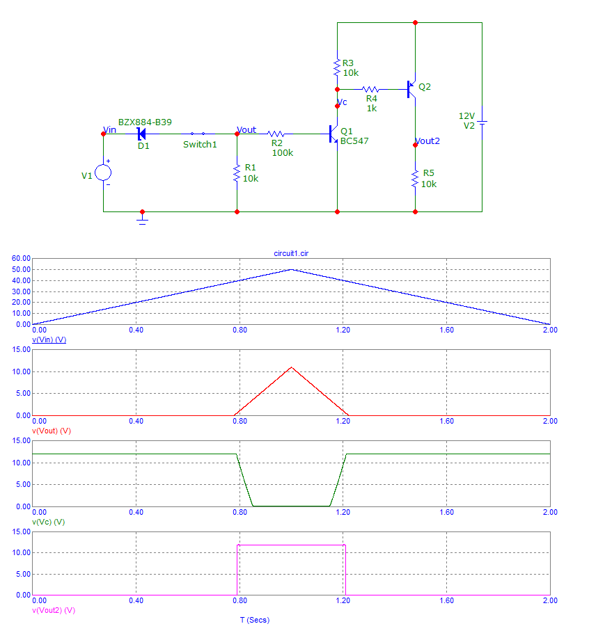
Just a couple of BJTs and a zener plus some resistors are needed to be reasonably accurate: -

enter image description here

\$\endgroup\$
1
\$\begingroup\$

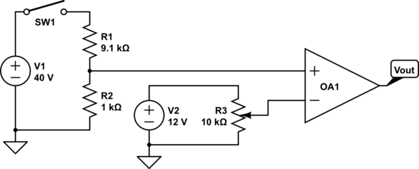
You could do something like this with a push-pull rail-to-rail comparator. You could add in debounce for the switch and/or move it to the low-voltage output of the resistor divider if it can't handle 60V. This assumes that your 40-60V won't go much above 60V, that you can handle some threshold drift with temperature, that your 40-60V input can be referenced to the comparator, etc.

schematic

simulate this circuit – Schematic created using CircuitLab

\$\endgroup\$
2
  • \$\begingroup\$ Thank you for this. Why wouldn't the 40-60V input be able to reference to the comparator? Considering its voltage has been divided down significantly. \$\endgroup\$
    – Hasman404
    Commented Oct 24, 2022 at 20:13
  • 2
    \$\begingroup\$ Meaning that you are able to tie the ground of the 40-60V input (battery?) to the same ground as the 12V supply. \$\endgroup\$
    – vir
    Commented Oct 24, 2022 at 20:16
1
\$\begingroup\$

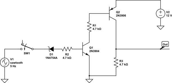
Do you really need the precision of a opamp/comparator?
How about this instead?

schematic

simulate this circuit – Schematic created using CircuitLab

The "sawtooth" V1 is just for simulation so you can see it switching on at 40V and off below that.
D1 is a 39V zener, so the output will probably turn on at about 39.6V - if that's a problem then add a schottky diode in series (forward-biased ofc).

\$\endgroup\$

Your Answer

By clicking “Post Your Answer”, you agree to our terms of service and acknowledge you have read our privacy policy.

Not the answer you're looking for? Browse other questions tagged or ask your own question.