added 13 characters in body
Source Link
ocrdu
  • 9.3k
  • 23
  • 32
  • 42

I'm trying to implement a autocorrelation module into my FPGA. I have been doing some reattach acrossresearch on the internet and there are some complicated and advanced methods that use a Fast Fourier Transform (FFT) to do the autocorrelation. 

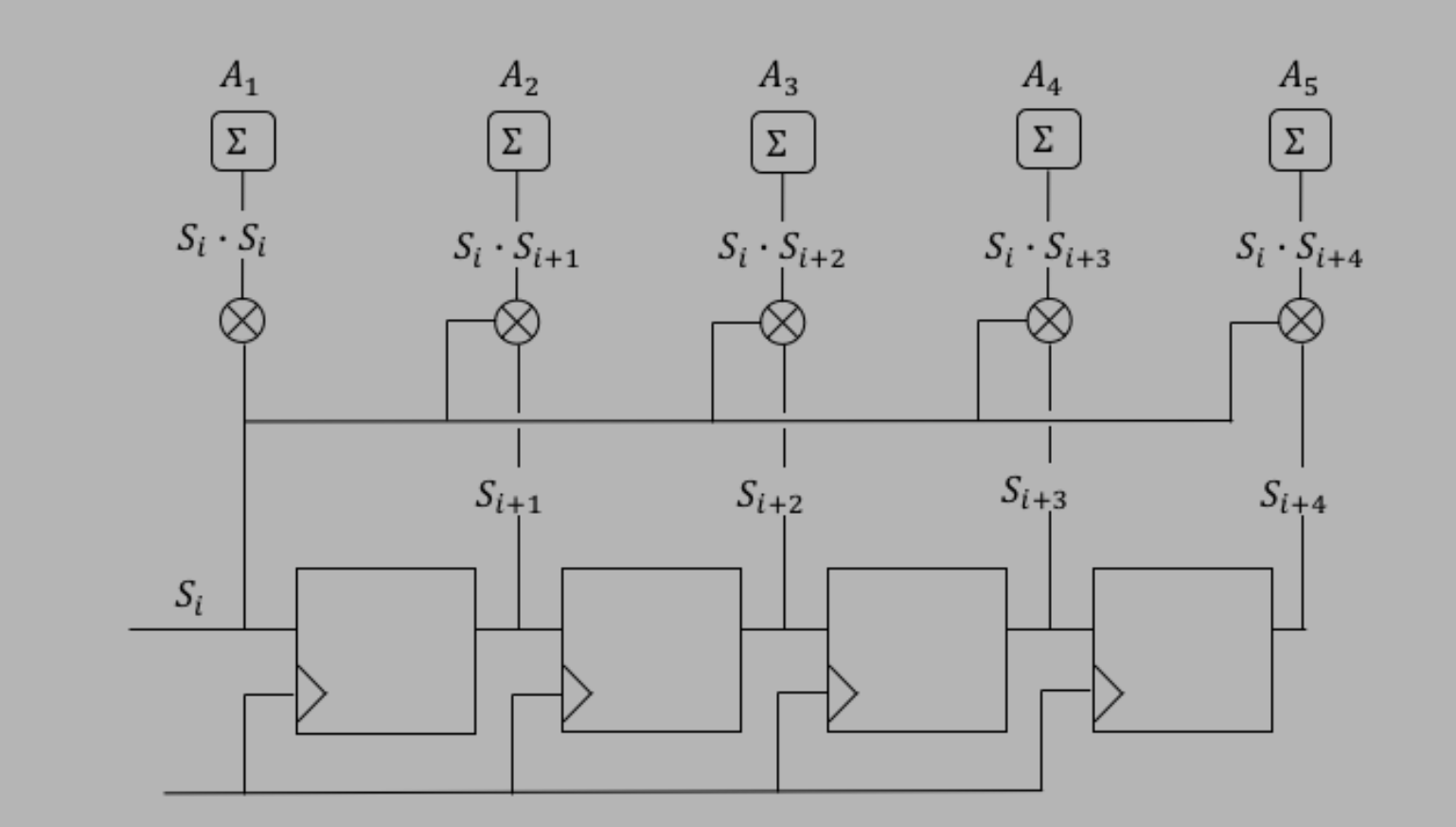
However, all I need is a simple implementation, nothing too fancy. I came across this digital logic site that had shown ahas this diagram as:

Design from autocorrelation website

Essentially, what I got out of this was that we chain D-Flipflip-Flopsflops (DFF) to create a shift register. From there we pull from the shift register or different DFFs and run them into a multiplier with the original \$S_{i}\$Si, then add the output. So my implementation from a program called digital is this:

Implementation using Digital application

Which I believe is the same, however, I am noticing some variations. I added more DFFs because I want to be able to correlate more bits. I also am not really sure if I implemented the "Sums" correctly,correctly; I also skipped the fist add from the first multiply for this reason. 

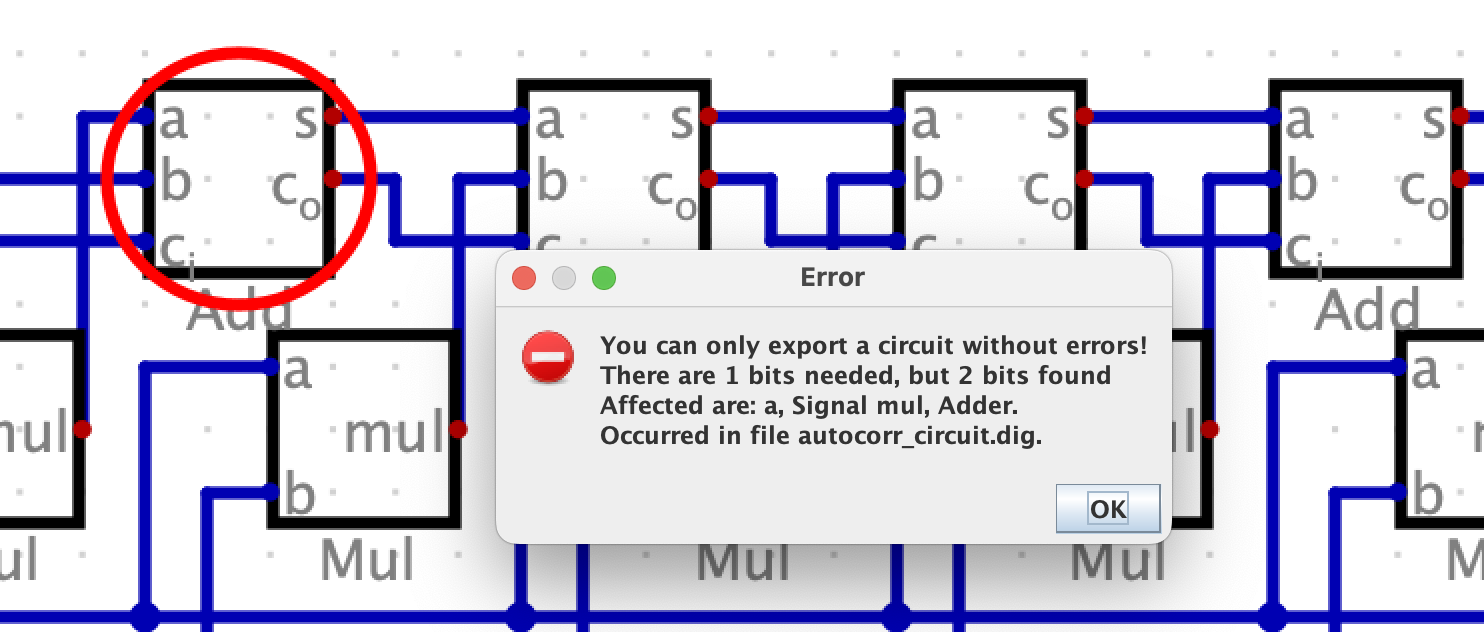
Some other issues I had include issues from the program. I ultimately usedused this program because I can take the design and get Verilog code out of it. But when I try to export as Verilog I get the error:

Verilog import error

Can anyone help confirm if I'm on the right track with this implementation or if it is correct.? It seems like the first adder is having issues but I am also unsure of what the first \$C_{i}\$Ci would be. In verilogVerilog I could just set it to a 0 bit, but I am not sure how to do that in a design.

I'm trying to implement a autocorrelation module into my FPGA. I have been doing some reattach across the internet and there are some complicated and advanced methods that use a Fast Fourier Transform (FFT) to do the autocorrelation. However, all I need is a simple implementation, nothing too fancy. I came across this digital logic site that had shown a diagram as:

Design from autocorrelation website

Essentially what I got out of this was we chain D-Flip-Flops (DFF) to create a shift register. From there we pull from the shift register or different DFFs and run them into a multiplier with the original \$S_{i}\$, then add the output. So my implementation from a program called digital is this:

Implementation using Digital application

Which I believe is the same, however, I am noticing some variations. I added more DFFs because I want to be able to correlate more bits. I also am not really sure if I implemented the "Sums" correctly, I also skipped the fist add from the first multiply for this reason. Some other issues I had include issues from the program. I ultimately used this program because I can take the design and get Verilog code out of it. But when I try to export as Verilog I get the error:

Verilog import error

Can anyone help confirm if I'm on the right track with this implementation or if it is correct. It seems like the first adder is having issues but I am also unsure of what the first \$C_{i}\$ would be. In verilog I could just set it to a 0 bit but not sure how to do that in a design.

I'm trying to implement a autocorrelation module into my FPGA. I have been doing some research on the internet and there are some complicated and advanced methods that use a Fast Fourier Transform (FFT) to do the autocorrelation. 

However, all I need is a simple implementation, nothing too fancy. I came across this digital logic site that has this diagram:

Design from autocorrelation website

Essentially, what I got out of this was that we chain D-flip-flops (DFF) to create a shift register. From there we pull from the shift register or different DFFs and run them into a multiplier with the original Si, then add the output. So my implementation from a program called digital is this:

Implementation using Digital application

Which I believe is the same, however, I am noticing some variations. I added more DFFs because I want to be able to correlate more bits. I also am not really sure if I implemented the "Sums" correctly; I also skipped the fist add from the first multiply for this reason. 

Some other issues I had include issues from the program. I ultimately used this program because I can take the design and get Verilog code out of it. But when I try to export as Verilog I get the error:

Verilog import error

Can anyone help confirm if I'm on the right track with this implementation or if it is correct? It seems like the first adder is having issues but I am also unsure of what the first Ci would be. In Verilog I could just set it to a 0 bit, but I am not sure how to do that in a design.
I'm trying to implement a autocorrelation module into my FPGA. I have been doing some reattach across the internet and there are some complicated and advanced methods that use a Fast Fourier Transform (FFT) to do the autocorrelation. However, all I need is a simple implementation, nothing too fancy. I came across this digital logic site that had shown a diagram as: Design from autocorrelation website

Design from autocorrelation website

Essentially what I got out of this was we chain D-Flip-Flops (DFF) to create a shift register. From there we pull from the shift register or different DFFs and run them into a multiplier with the original \$S_{i}\$, then add the output. So my implementation from a program called digital is this: enter image description here

Implementation using Digital application

Which I believe is the same, however, I am noticing some variations. I added more DFFs because I want to be able to correlate more bits. I also am not really sure if I implemented the "Sums" correctly, I also skipped the fist add from the first multiply for this reason. Some other issues I had include issues from the program. I ultimately used this program because I can take the design and get verilogVerilog code out of it. But when I try to export as verilogVerilog I get the error:

enter image description hereVerilog import error

Can anyone help confirm if I'm on the right track with this implementation or if it is correct. It seems like the first adder is having issues but I am also unsure of what the first \$C_{i}\$ would be. In verilog I could just set it to a 0 bit but not sure how to do that in a design.

I'm trying to implement a autocorrelation module into my FPGA. I have been doing some reattach across the internet and there are some complicated and advanced methods that use a Fast Fourier Transform (FFT) to do the autocorrelation. However, all I need is a simple implementation, nothing too fancy. I came across this digital logic site that had shown a diagram as: Design from autocorrelation website

Essentially what I got out of this was we chain D-Flip-Flops (DFF) to create a shift register. From there we pull from the shift register or different DFFs and run them into a multiplier with the original \$S_{i}\$, then add the output. So my implementation from a program called digital is this: enter image description here

Which I believe is the same, however, I am noticing some variations. I added more DFFs because I want to be able to correlate more bits. I also am not really sure if I implemented the "Sums" correctly, I also skipped the fist add from the first multiply for this reason. Some other issues I had include issues from the program. I ultimately used this program because I can take the design and get verilog code out of it. But when I try to export as verilog I get the error:

enter image description here

Can anyone help confirm if I'm on the right track with this implementation or if it is correct. It seems like the first adder is having issues but I am also unsure of what the first \$C_{i}\$ would be. In verilog I could just set it to a 0 bit but not sure how to do that in a design.

I'm trying to implement a autocorrelation module into my FPGA. I have been doing some reattach across the internet and there are some complicated and advanced methods that use a Fast Fourier Transform (FFT) to do the autocorrelation. However, all I need is a simple implementation, nothing too fancy. I came across this digital logic site that had shown a diagram as:

Design from autocorrelation website

Essentially what I got out of this was we chain D-Flip-Flops (DFF) to create a shift register. From there we pull from the shift register or different DFFs and run them into a multiplier with the original \$S_{i}\$, then add the output. So my implementation from a program called digital is this:

Implementation using Digital application

Which I believe is the same, however, I am noticing some variations. I added more DFFs because I want to be able to correlate more bits. I also am not really sure if I implemented the "Sums" correctly, I also skipped the fist add from the first multiply for this reason. Some other issues I had include issues from the program. I ultimately used this program because I can take the design and get Verilog code out of it. But when I try to export as Verilog I get the error:

Verilog import error

Can anyone help confirm if I'm on the right track with this implementation or if it is correct. It seems like the first adder is having issues but I am also unsure of what the first \$C_{i}\$ would be. In verilog I could just set it to a 0 bit but not sure how to do that in a design.

Source Link

Autocorrelation digital logic design

I'm trying to implement a autocorrelation module into my FPGA. I have been doing some reattach across the internet and there are some complicated and advanced methods that use a Fast Fourier Transform (FFT) to do the autocorrelation. However, all I need is a simple implementation, nothing too fancy. I came across this digital logic site that had shown a diagram as: Design from autocorrelation website

Essentially what I got out of this was we chain D-Flip-Flops (DFF) to create a shift register. From there we pull from the shift register or different DFFs and run them into a multiplier with the original \$S_{i}\$, then add the output. So my implementation from a program called digital is this: enter image description here

Which I believe is the same, however, I am noticing some variations. I added more DFFs because I want to be able to correlate more bits. I also am not really sure if I implemented the "Sums" correctly, I also skipped the fist add from the first multiply for this reason. Some other issues I had include issues from the program. I ultimately used this program because I can take the design and get verilog code out of it. But when I try to export as verilog I get the error:

enter image description here

Can anyone help confirm if I'm on the right track with this implementation or if it is correct. It seems like the first adder is having issues but I am also unsure of what the first \$C_{i}\$ would be. In verilog I could just set it to a 0 bit but not sure how to do that in a design.