1
\$\begingroup\$

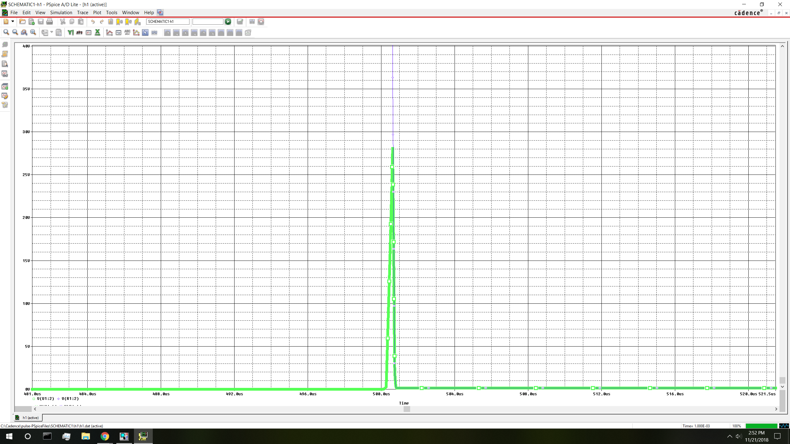
I'm testing a simple enough circuit on PSPICE. The zener has a BV = 220V, so the capacitor has a voltage of 220V until the switch closes. enter image description here
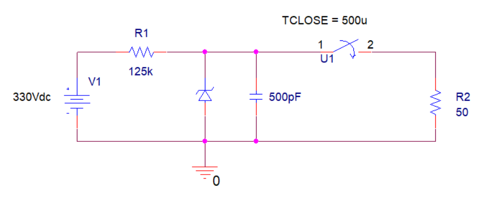
  • Using the time equation for voltage of a capacitor: Vc(t) = Vo * e^(-t/tau)

Vc(1ns) = 220V * e^(-1ns/50*500pF) = 211.37V

Vc(25ns) = 220V * e^(-25ns/50*500pF) = 80.93V

Vc(50ns) = 220V * e^(-50ns/50*500pF) = 29.77V

Vc(75ns) = 220V * e^(-50ns/50*500pF) = 10.95V

Vc(100ns) = 220V * e^(-50ns/50*500pF) = 4.02V

  • Calculate dV/dt:

1ns --> dV/dt = (220V - 211.37V)/1ns = 8.63E9

25ns --> dV/dt = (220V - 80.93V)/25ns = 5.56628E9

50ns --> dV/dt = (220V - 29.77V)/50ns = 3.8046E9

75ns --> dV/dt = (220V - 10.95V)/75ns = 2.787E9

100ns --> dV/dt = (220V - 4.02V)/100ns = 2.1598E9

  • And using the current equation for capacitors: Ic(t) = C*dV/dt

Ic(1ns) = 500pF*8.63E9 = 4.315A

Ic(25ns) = 500pF*5.56628E9 = 2.78A

Ic(50ns) = 500pF*3.8046E9 = 1.90A

Ic(75ns) = 500pF*2.787E9 = 1.3935A

Ic(100ns) = 500pF*2.1598E9 = 1.079A


Seems great. Unfortunately, PSPICE disagrees.

The peak voltage node R2 reaches after the switch closes is only around 28V. It's clear to see that based on the topology this is just one big voltage divider. There shouldn't be any voltage at all on the top node after the switch closes because the overwhelming majority of voltage is dropped across R1. This doesn't explain why the capacitor releases such a wimpy peak in voltage though.

enter image description here

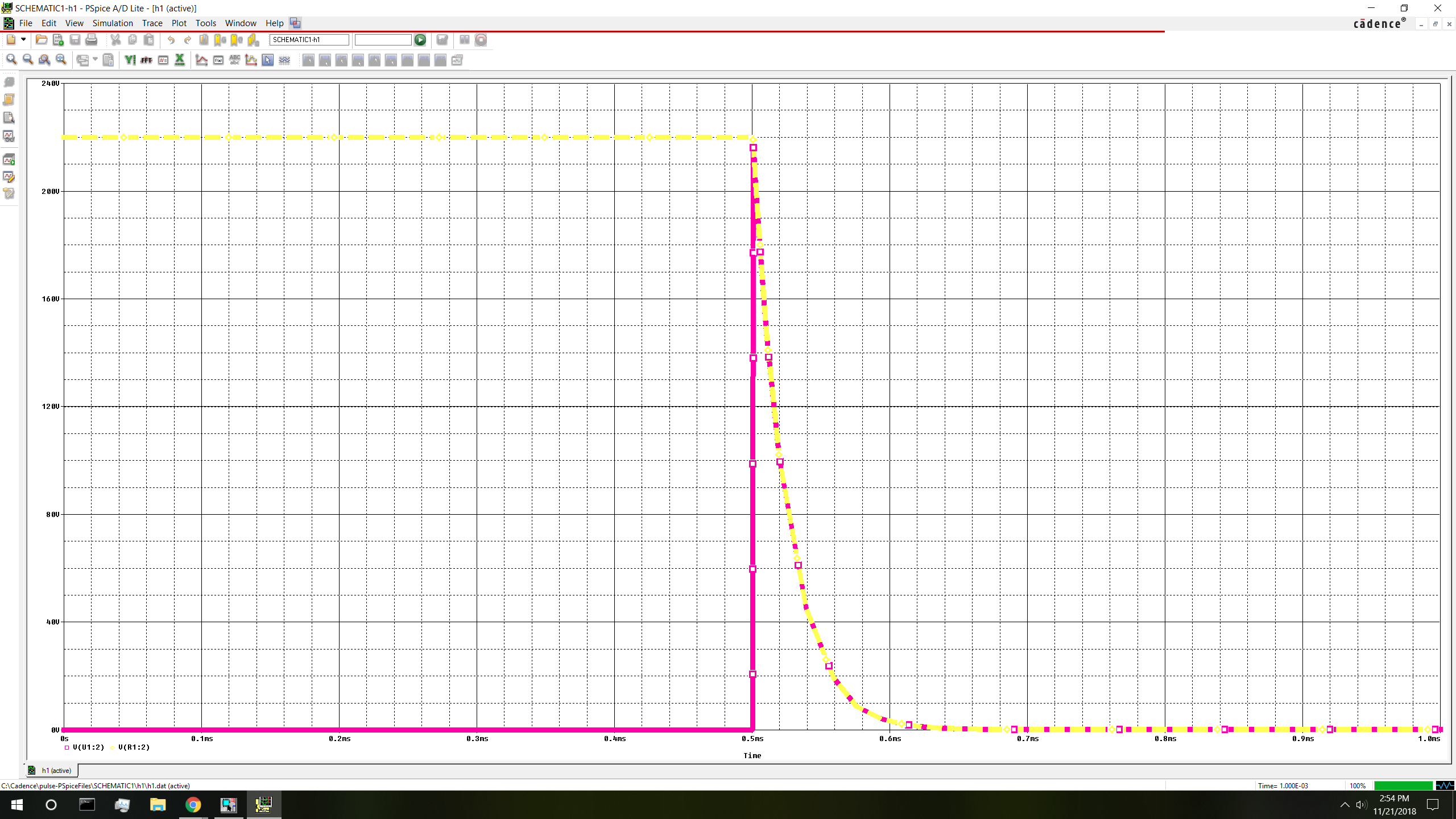
So I simply decide to test out 500nF, and poof! I get an output that I was expecting for the 500pF capacitor. But, I still don't understand why neither of these simulations discharges the capacitor within the expected time constant of 25ns(4) = 100ns. It should be almost completely discharged at 4tau.

Obviously PSPICE cannot be wrong. What am I missing here?

enter image description here

\$\endgroup\$
2
  • 3
    \$\begingroup\$ "Obviously PSPICE cannot be wrong." Hah... \$\endgroup\$
    – pipe
    Commented Nov 21, 2018 at 21:29
  • 1
    \$\begingroup\$ Your calculations for dV/dt and hence Ic are incorrect. dV/dt can be calculated directly by differentiating the equation for Vc and then substituting the desired values of t. Your calculations assume that Vc is falling linearly when it is actually falling exponentially. \$\endgroup\$
    – Barry
    Commented Nov 21, 2018 at 21:50

1 Answer 1

2
\$\begingroup\$

How do you account for the switch in your hand calculations?

Spice has to do that. There is no such thing as a discontinuity when you are trying to do a continuous time simulation. Unless specialized algorithms are used, discontinuities require infinitesimally small time steps which require infinite time to simulate. For many algorithms this extends to discontinuities even in the derivatives.

Spice must be using some form of continuous model for the switch. Very likely a variable resistor that goes from very large to very small in a short amount of time. Faster than your 500nF capacitor time constant, but slower than your 500pF one.

\$\endgroup\$
4
  • \$\begingroup\$ +1, it is clear from first OP's picture that the turn-on time of the switch model is something like 0.5us, so the voltage on load reaches only certain small amplitude before the switch fully closes, while the RC is just 25 ns. \$\endgroup\$ Commented Nov 21, 2018 at 21:54
  • \$\begingroup\$ In my actual circuit I intend to be using a power mosfet as the switch. I couldn't figure out how I would send specific signals to the Mosfet gate in Cadence and resorted to using the switch. Is there a way to send specific signals to gates in Cadence? \$\endgroup\$
    – snowg
    Commented Nov 22, 2018 at 17:15
  • 1
    \$\begingroup\$ Use a PWL or pulse voltage source. \$\endgroup\$ Commented Nov 22, 2018 at 17:50
  • \$\begingroup\$ Also, despite the property of the switch I was able to remedy the problem by editing the Ic parameter of the capacitor. Ic determines the starting voltage of the capacitor, setting it equal to 220V gave me what I was expecting. \$\endgroup\$
    – snowg
    Commented Nov 22, 2018 at 17:51

Your Answer

By clicking “Post Your Answer”, you agree to our terms of service and acknowledge you have read our privacy policy.

Not the answer you're looking for? Browse other questions tagged or ask your own question.