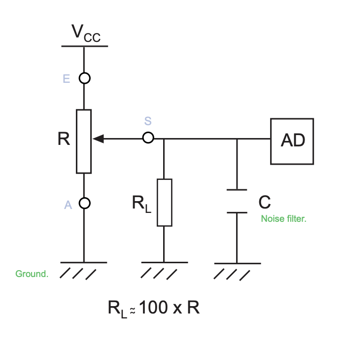
In the reference circuit from this datasheet for a potentiometer, what is RL for? Why did they pick 100 x R? Bonus question, how do I pick a good value for C?
-
1\$\begingroup\$ what are you building? \$\endgroup\$– jsotolaCommented Jan 23, 2019 at 5:05
-
\$\begingroup\$ Heh, @jsotola, sorry. :) In my head I was thinking voltage divider and so R1 and R2. I'll change the title. This is going into an analog input pin of an ATTiny85 to set the brightness of an LED. \$\endgroup\$– D. PatrickCommented Jan 23, 2019 at 5:20
-
2\$\begingroup\$ I think it's distracting if you start talking about what you're building. It will invite people to not answer the question but instead say "I would do it like this". It's a good and clear stand-alone question. \$\endgroup\$– pipeCommented Jan 23, 2019 at 5:48
-
\$\begingroup\$ All they are really showing is that to have a linear or log pot meet their profile (or nearly so) you need to be aware of the input resistance of the load. A good rule of thumb is to ensure that the wiper load (input impedance/resistance of following circuit) is 100 times the pot value \$\endgroup\$– Jack CreaseyCommented Jan 23, 2019 at 6:08
-
\$\begingroup\$ To me it is a nonsense to add RL = 100xR into this circuit. I adds no functionality whatsoever. I could see a reason to keep a current in the "S" branch, to avoid oxydation of the contact. \$\endgroup\$– d-stroyerCommented Jan 23, 2019 at 13:12
2 Answers
It isn't "for" anything. The manufacturer is simply saying that in order to get the rated performance out of the potentiometer, whatever load is connected to the wiper should be greater than 100× the value of the potentiometer.
The capacitor, in conjunction with the effective source resistance of the potentiometer, creates a low-pass filter. Since the source resistance varies with the wiper position, the cutoff frequency varies accordingly. The maximum source resistance occurs at the center of the range, with a value of 1/4 the potentiometer value (assuming both ends are connected to voltage sources), and it decreases toward either end. Select the capacitor value so that the cutoff frequency stays in the range you need.
-
\$\begingroup\$ What's the AD box? I assumed it was for Analog-Digital (converter). \$\endgroup\$ Commented Jan 24, 2019 at 21:14
-
1\$\begingroup\$ Yes, that would be my guess, too. The potentiometer is being used (hypothetically) as a position sensor, either for a UI (user interface) or as part of a machine. \$\endgroup\$ Commented Jan 24, 2019 at 21:22
-
\$\begingroup\$ why would they run a load off the output of the pot? I guess they’re saying that if you have a load and are sensing then the load has to be at least 100x or you’ll mess up the ADC input? That seems kind of weird. \$\endgroup\$ Commented Jan 24, 2019 at 23:01
It is probably serving as a pulldown resistor to the capacitor. these are quite common at least in the circuits I've seen.

