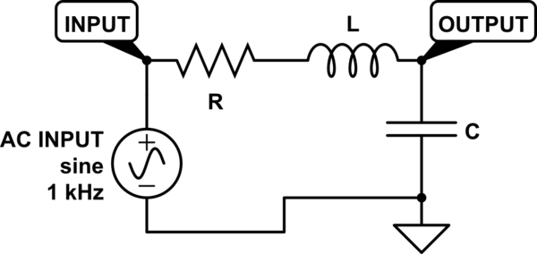
I'm trying to refresh my knowledge on RLC filters, and I'm using MATLAB to model it. Given an RLC circuit with the elements in series, taking the output at the capacitor should result in a 2nd-order low pass filter. You can see the circuit I'm trying to replicate here.

simulate this circuit – Schematic created using CircuitLab
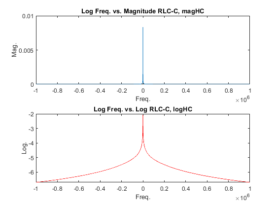
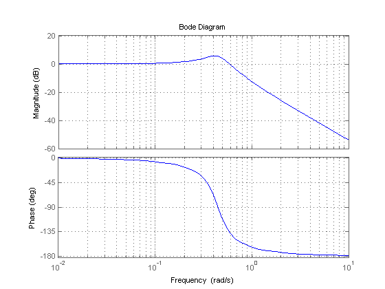
However, the results don't seem to match up with what is expected. I'm using this Filter Design Tool as a check to see if my work matches up with the same values, but the results that I got, when plotted, doesn't make sense. Rather than getting the low pass filter, I seem to have gotten a Notch Filter, which doesn't make sense. I'm sure I got my transfer function right, but what in my code is causing this outcome? Could it be my component values are impractical that's causing this?
EDIT: To better show what I'm talking about, I cleaned up my code a bit, and below is an image of what I'm getting for the bode plot with the exact code. As you can see, it is definitely not a low pass filter as what I expected:
clc; clear all; close all; clc;
omega=-1.*(10.^6):100:1.*(10.^6);    log_omega = log10(omega);
%Limits
nzero=zeros(size(omega));

L = 0.005;     R = 1200;      C =  (10.^-3) ;

%Terms    %Solutions
alpha = (R./(2.*L));        omega_z = 1./sqrt(L.*C);
s1 = (-1.*alpha.*alpha) + sqrt((alpha.^2)-(omega_z.^2));
s2 = (-1.*alpha.*alpha) - sqrt((alpha.^2)-(omega_z.^2));
f1 = s1./(2.*pi);    f2 = s2./(2.*pi);

%Denominator Impedances
ZR = R;
ZL = j.*omega.*L;
ZC = 1./(j.*omega.*C);
denom = ZR + ZL + ZC;

%Function
HC = (ZC)./ denom;
magHC=abs(HC);
logHC=log10(magHC);

subplot(2,1,1);
plot(omega,magHC);title('Log Freq. vs. Magnitude RLC-C, magHC');
xlabel('Freq.'); ylabel('Mag.');      hold on;

subplot(2,1,2);
plot(omega,logHC,'r');
title('Log Freq. vs. Log RLC-C, logHC'); xlabel('Freq.'); ylabel('Log.');
hold on;


H = ZR./(ZR+ZL+ZC)) and in that case some sort of resonant behavior seems reasonable. \$\endgroup\$