0
\$\begingroup\$

First a quick descripton of my circuit:

The inverting amplifier amplifies by 20dB, the input voltage is a sinus signal with the Frequency 10 kHz and the peak to peak voltage is 200mV or 10V. The used amplifier is a OP177G. I've measured the Fast Fourier Transformation (FFT) of the output Signal. The Bandwidth of the amplyfier is 60 kHz. The outputsignal gets altered by the Slewrate for frequencys greater than 477 kHz if the input voltage is 200 mV and 9,5 kHz if the input voltage is 10 V. I only look at frequenys lower than 60 kHz cause im only interested in the altering by the slew-rate.

Now to the interpretation and my question:

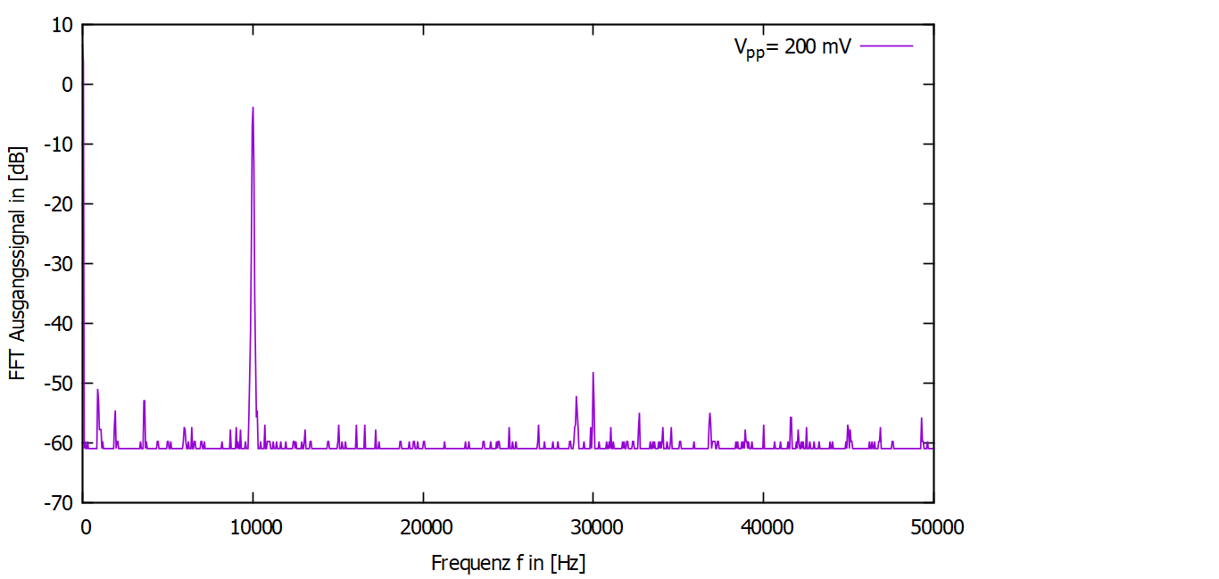
If the input voltage is 200 mV I get a big peak at 10 kHz in the Fourierspectrum and no other peaks, as expected. The frequency of the input signal is way lower than the critical frequency 447 kHz, so I get a sinus signal as an output signal.

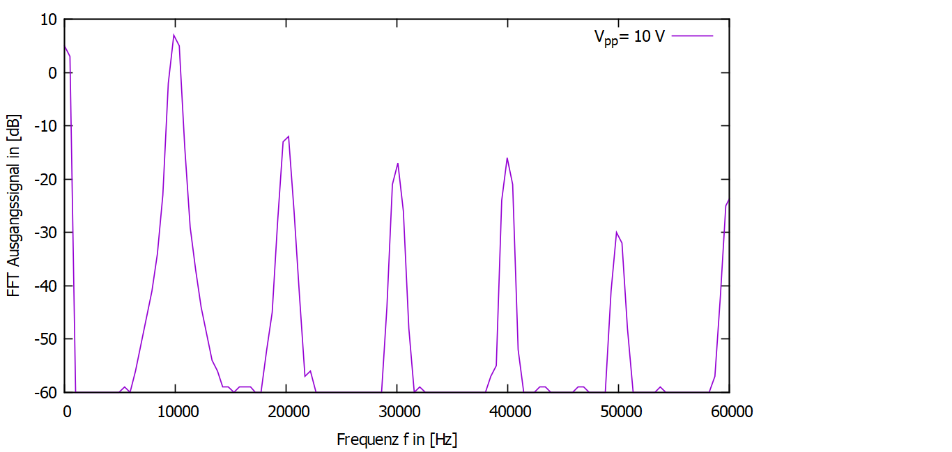
If the input voltage is 10 V, the critical frecueny 9,5 kHz is lower than the frequency of the input signal so my output signal should be a triangular function an therefore there should only be peaks at 10 kHz, 30 kHz, 50 kHz and so on after the fourier transformation. But I also have peaks at even multiples e.x. 20 kHz, 40 kHz, ... . I dont get why this is the case, because there are none in the fourier transformation of a triangular function?

Here is my plot for the input voltage 200 mV: This is the plot of the fourierspectrum for an input voltage of 200 mV. Here is my plot for the input voltage 10 V: This is the plot of the fourierspectrum for an input voltage of 10 V.
\$\endgroup\$

1 Answer 1

0
\$\begingroup\$

Not looking at your design , I can see your 1) slew rate limiting AND/OR 2) hFE is unequal.

  1. Each polarity of push-pull driver may have a different impedance and thus the asymmetry causes even harmonic distortion to you added to anticipated odd harmonics.

    -You should realize the GBW requirements increase dramatically when you include specs for THD at a signal in the same decade as your BW, since you have very little excess gain to feedback for linear error correction.

    Also it is important to remember that when designing sharp or high Q RC active filters this also raises the GBW requirements significantly, much higher than you may expect due to phase shifting 1 decade below breakpoint becomes more critical with higher Q filters like Chebychev vs Bessel. TI's Active Filter designer tells GBW requirements for each stage.

. 2. Unequal current gain is another reality near current limits for high voltage outputs. This affects the THD by adding even & odd harmonics.

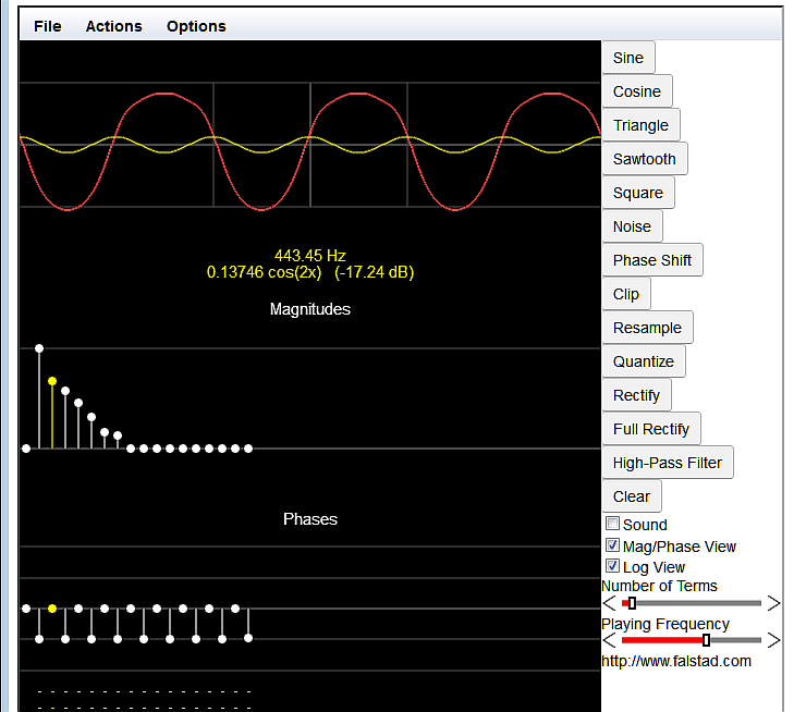
e.g. enter image description here

(Disregard the frequency, I adjust the harmonic levels to resemble yours)

\$\endgroup\$
1
  • \$\begingroup\$ What do you mean by the slew-rate limiting is uneven? The Slewrate of the OP177G is \$SR=\frac{0,3 V}{\micro s}\$ . So the critical frequencys for 200mV is \$\frac{SR}{\pi \cdot \ U_{pp}}=477 \ kHz\$ and for 10 V its \$\frac{SR}{\pi \cdot \ U_{pp}}=9,5 \ kHz\$. And the critical frecuency caused by the Gain-Bandwith Product f_GBW is proportional to f_GBW. So if f_GBW gets higher it should have even less influence to my problem? \$\endgroup\$
    – Joe1999
    Commented Dec 8, 2019 at 23:37

Your Answer

By clicking “Post Your Answer”, you agree to our terms of service and acknowledge you have read our privacy policy.

Not the answer you're looking for? Browse other questions tagged or ask your own question.