I have a project for which I need to be able to read Caller ID from the telephone line.
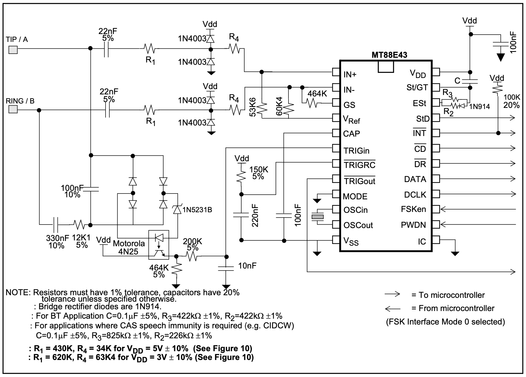
I found MT88E43B chip that does FSK demodulation. They have an application circuit in their datasheet (specifically page 15, Figure 11).
I have assembled it using the values for 5V power supply and increased speech immunity (C=0.1μF, R3=825K, R2=226K, R1=430K, R4=34K).
The circuit works great when connected directly to the VoIP device at the house, it can decode the Caller ID and I can successfully get it in the microcontroller for further processing.
However, if I connect it to the house wiring when the VoIP device is wired through the patch panel, it reads gibberish from the line.
I did the testing and found out that a regular telephone, or even a modem, can easily read and decode the Caller ID signal when connected to the same outlet, while this circuit can't.
I did some measurements, and of course there is a lot of noice on the line in range from ~200 Hz to ~5 Khz that runs on top of 60 Hz. I guess I'm missing some sort of a filter before the circuit, or it needs some input adjustments.
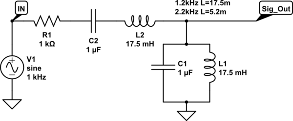
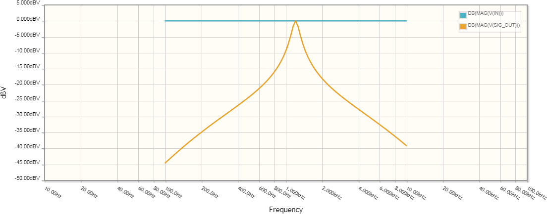
At this point I tried using a ferrite choke and a DSL filter with no help. Currently my best idea is to use 2 parallel LC bandpass filters for 1200 and 2200 Hz respectively, and I'm looking at 2nd order Butterworth because of its simplicity.
It's a hobby project, and I don't have enough knowledge to figure it out on my own, so I would highly appreciate any advice!
Here's the schematic I'm talking about:


