3
\$\begingroup\$

I have a project for which I need to be able to read Caller ID from the telephone line.

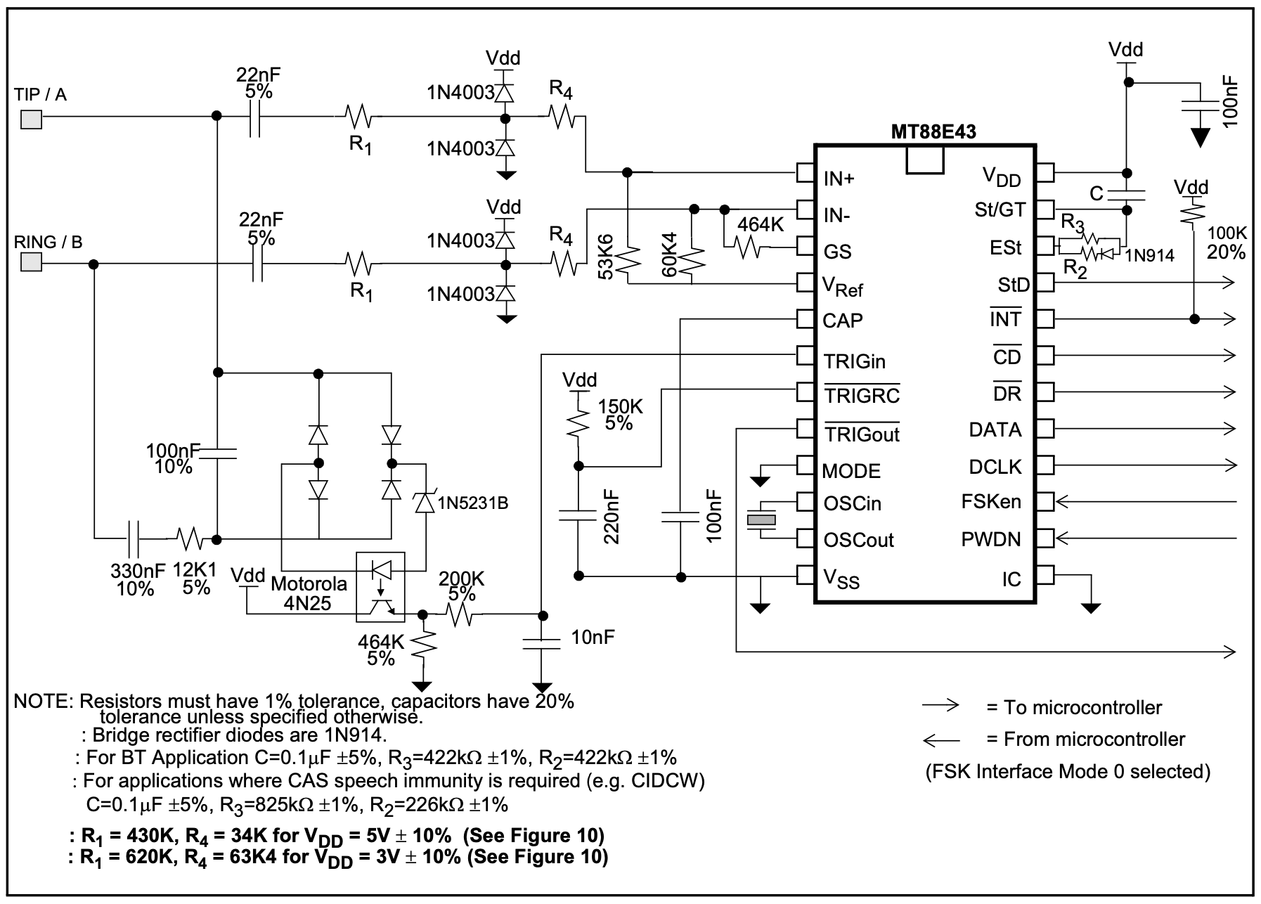
I found MT88E43B chip that does FSK demodulation. They have an application circuit in their datasheet (specifically page 15, Figure 11).

I have assembled it using the values for 5V power supply and increased speech immunity (C=0.1μF, R3=825K, R2=226K, R1=430K, R4=34K).

The circuit works great when connected directly to the VoIP device at the house, it can decode the Caller ID and I can successfully get it in the microcontroller for further processing.

However, if I connect it to the house wiring when the VoIP device is wired through the patch panel, it reads gibberish from the line.
I did the testing and found out that a regular telephone, or even a modem, can easily read and decode the Caller ID signal when connected to the same outlet, while this circuit can't.

I did some measurements, and of course there is a lot of noice on the line in range from ~200 Hz to ~5 Khz that runs on top of 60 Hz. I guess I'm missing some sort of a filter before the circuit, or it needs some input adjustments.

At this point I tried using a ferrite choke and a DSL filter with no help. Currently my best idea is to use 2 parallel LC bandpass filters for 1200 and 2200 Hz respectively, and I'm looking at 2nd order Butterworth because of its simplicity.

It's a hobby project, and I don't have enough knowledge to figure it out on my own, so I would highly appreciate any advice!

Here's the schematic I'm talking about:

MT88E43B Application Circuit

\$\endgroup\$
2
  • 1
    \$\begingroup\$ What is the specific frequency you need to do demodule? Instead of a Butterworth, you may just want a resonant filter. A 4th order would be relatively easy with inductor and capacitors. Typically low cost signal over power line devices used 4th order resident filters as well for this type of operation. \$\endgroup\$
    – MadHatter
    Commented Feb 27, 2020 at 23:30
  • \$\begingroup\$ @MadHatter Thank you for the suggestion! There are two frequencies involved — 1200 Hz and 2200 Hz for logical mark and space respectively and I need to basically isolate them filtering out the rest. \$\endgroup\$
    – zysoft
    Commented Feb 28, 2020 at 2:26

1 Answer 1

1
+50
\$\begingroup\$

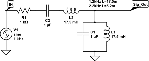
Not sure on the exact requirements for FSK and caller ID, but if this is anything like ~50kHz data over power line systems, Design guides often suggest a 4th order LC bandpass filter as a cheap starting point.

This should be simple enough to test out.

schematic

simulate this circuit – Schematic created using CircuitLab

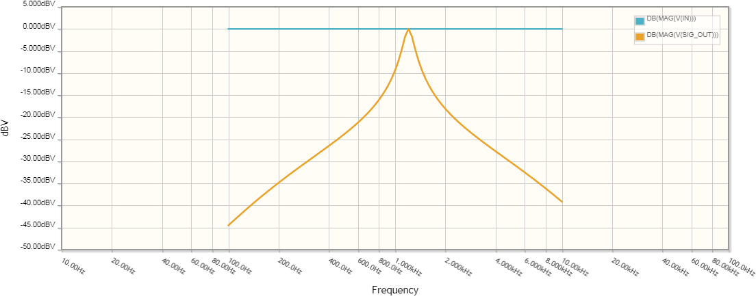
enter image description here

Notes:

  • This is a starting point. R1 may need adjustment depending on how much your circuit loads the filter etc. Good news is it is easy to simulate this, so you can rest out different values virtually.
  • You no longer need a blocking capacitor from your original circuit since C2 does that for you.
  • I believe this would take the place of R1 and the 22nF capacitor in the above circuits.

You might also not want to attach this circuit to ground, you would have to study how do you supporting passives I see on those inputs are set up. You will have to study more the purpose of R1, R4 and the surrounding components. They are tightly specified at 1% and I'm not sure why.

\$\endgroup\$
6
  • \$\begingroup\$ Thank you! I've simulated it in LTSpice and it seems to provide great frequency response! I will build it and try on the real line. Could you point me to the math behind it please? \$\endgroup\$
    – zysoft
    Commented Feb 28, 2020 at 2:40
  • \$\begingroup\$ Google LC resonant filter. f=1/2πSqrt(LC) \$\endgroup\$
    – MadHatter
    Commented Feb 28, 2020 at 5:03
  • \$\begingroup\$ Found some, thanks! \$\endgroup\$
    – zysoft
    Commented Feb 28, 2020 at 5:09
  • \$\begingroup\$ Thank you for your help! The last thing I can't figure out is how to combine two of these filters into a single dual-band one, since I need both frequencies to be able to pass. I would appreciate any advice! \$\endgroup\$
    – zysoft
    Commented Mar 2, 2020 at 22:32
  • \$\begingroup\$ Do you need both frequencies on both lines? I figured 1 frequency per line? If so, maybe this is not the best approach. Otherwise, you could put the 2 in parallel, but that's a lot of components for what your doing. \$\endgroup\$
    – MadHatter
    Commented Mar 3, 2020 at 0:21

Your Answer

By clicking “Post Your Answer”, you agree to our terms of service and acknowledge you have read our privacy policy.

Not the answer you're looking for? Browse other questions tagged or ask your own question.