I believe you have a fundamental misunderstanding.
As a general understanding, it is true that you need a closed circuit. This is most commonly taught by the use of DC circuits, which do require "visible" or "direct" connectors that show a completely closed circuit. However, as you move into AC circuits, you need to learn that even "incomplete" (open) circuits are (or can be) closed, via various capacitance effects.
You need to be aware that a capacitor is made of two separated conductors, and although they are physically separated, as far as AC is concerned, they are electrically connected. In other words, any time you see a capacitor (-| |-), as far as AC (or pulsed DC) is concerned, it acts as if the plates are shorted (-|-|-).
As far as the antenna is concerned, the top of the antenna is connected to one side of a "virtual capacitor and the other side of the "virtual" capacitor is connected to ground. Since the bottom of the antenna is also connected to ground (by various methods), a "closed" circuit is formed.
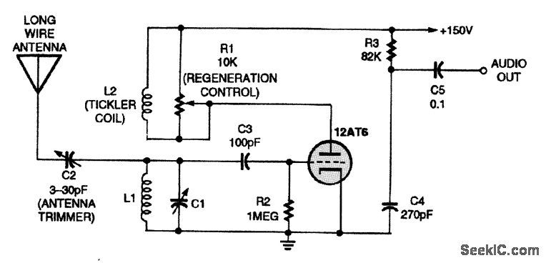
Using the circuit with the vacuum tube as an aid, if you use a "small" capacitor and connect it to the top of the antenna, and the other side of the capacitor to ground, you will form a closed loop antenna. This allows the electromagnetic waves to induce a small current in the loop antenna. This current then induces a voltage across the capacitor connected to the control grid of the vacuum tube. The grid and the cathode of the vacuum tube also form a capacitor, so as the grid charges and discharges, it controls (gates) a larger current from the cathode to the plate, thereby the changes get amplified.
The explanation for pulsing DC, is the same as above. The pulsing DC charges and discharges one side of the capacitor which induces a voltage on the other side of the capacitor... thereby the changes get amplified.
EDIT: After reading your questions once more, I detected another misunderstanding on your part. You say, "there is a single wire from the antenna to the demodulator input." This is not true. There are three "closed loop" circuits involved: 1 antenna closed loop, 2 control grid loop, and 3 plate output loop.
1 Is formed by antenna wire, ant. adj. cap C2, resonant tank L1 C1, and ant - ground (virtual) cap Cv.
2 Is formed by res. tank L1 C1, feed cap C3, and grid - cath cap Cg.
3 Is formed by cath - plate cap Cp, plate res. R1, output cap C5, and load res. Rl. (Note, several of these symbols are not on the designated circuit)


