simulate this circuit – Schematic created using CircuitLab
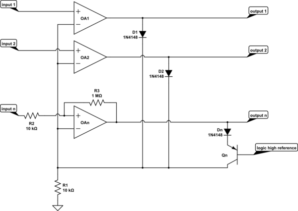
It's intended that all channels are identical. However, I've drawn channels 1 and 2 as the simplest possible, and left channel n to receive embellishments.
Consider all inputs except input 1 low. Amplifier 1 works as a follower, with its output a diode D1 drop above its negative input, R1 pulling a modest current through the diode. All other amplifier outputs will be at the negative rail, with their diodes reverse biassed.
As input 2 increases in voltage, it will eventually exceed the common reference voltage on R1, OA2 output will go high, pulling the common reference up to its input voltage, which will send amplifier 1 output low.
If we assume a sufficiently low impedance driving the inputs, I've shown on channel n how a sniff of hysteresis can be applied to the input.
The active output is a diode drop above the input voltage. The inactive outputs are near the negative rail.
To make this easily discriminated by logic, the inputs need to be guaranteed to stay some reasonable voltage above the negative rail. This will happen automatically if the inputs are strictly positive, and the amplifiers receive a negative rail.
With sufficient positive rail available, the diodes could be replaced by elements with a larger voltage drop, for instance several series diodes, or a LED, to increase the voltage excess of the output over the input. Using LEDs would make a nice self-indicating circuit, as long as the LED reverse breakdown was not exceeded, or they were protected by a proper diode in series. If they were inputs to optocouplers, they could be used to drive logic easily.
In an effort to get better logic levels out of the system, I've added Qn. It works as a cascode, transferring the amplifier output current to R1, but only when the output voltage is about 2 diode drops above the logic high reference voltage. Dn could be omitted, as long as the reverse VBE limit, usually around 5v or so for silicon, is not exceeded when the output is low. This now ensures that the outputs are nearly negative rail for low, and logic high reference + 1.4v for high. It does increase the loop gain of the system, so might compromise stability. I'd need to think about that. A resistor in series with Qn emitter would control the gain, and while it would destroy the relatively constant output high voltage, at least the output high voltage is guaranteed to be above a certain voltage, regardless of how low the winning input voltage is.
An essentially identical scheme can be configured to select the smallest input voltage
13 silicon diodes and 4 quad opamps, I'm sure the cost would be much less than 2 USD/EUR/GBP, probably less than one!
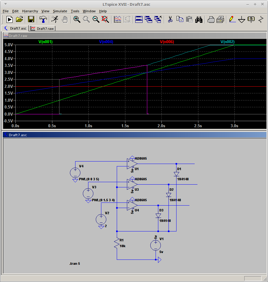
It's so straightforward you can see it works by inspection, but here is a SPICE simulation for those who doubt their analytic abilities.

I never got around to building this, because I went straight for the thing I actually wanted, which was differential amplifiers in a minimum selecting arrangement to show me the minimum cell voltage in a 5S Lipo battery.


