0
\$\begingroup\$

I would like to use the interface on link below. I tried to do exactly same except output because to test first, I gave output to LED from microcontroller.

My question is with MC1489. When i connected 5V to VCC, I always get continous signal from 3rd pin (1Y on datasheet.) It doesn't matter if I connect 24V input to pin (1A) or not.

How should I connect it exactly to control over output pin? What does the control pin do? In the interface schematic there is no connection to the control pin. Should it float or what should I connect there?

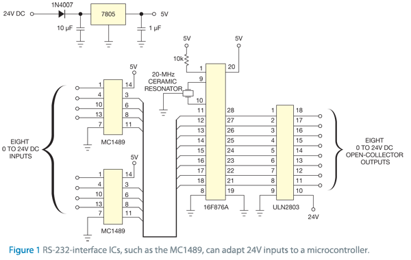
24Vdc to 5VDC Interface

enter image description here

Datasheet

\$\endgroup\$
6
  • \$\begingroup\$ Are you seriously using Jim Thompson's MC1489 today???? Seriously? The control lines allow you to vary the input thresholds. Have you read the datasheet? \$\endgroup\$
    – jonk
    Commented Aug 5, 2020 at 6:37
  • \$\begingroup\$ @jonk I don't know how i can make 24V input compatible with 5V MCU. So, I try whatever i find. Do you have any recommendation instead? \$\endgroup\$
    – alfonso
    Commented Aug 5, 2020 at 6:41
  • \$\begingroup\$ All you need to do is design a simple BJT receiver with from 3k to 7k input impedance and tolerating about 25 V worst case at the input. It's dead trivial. The MC1489 runs "hot." Not as horribly hot as the MC1488 transmitter. But pretty hot, just the same. It's 1970's technology from Jim, and after my experience with them in the early 1980's, I'd be looking ANYWHERE else, right now. The MC1488 and MC1489 are on my "never use again" list. (They meet specs very well. But they burn power like it's free.) \$\endgroup\$
    – jonk
    Commented Aug 5, 2020 at 6:44
  • 1
    \$\begingroup\$ Look here for example. (You don't need the diode and capacitor that is connected to the RS-232 pin.) \$\endgroup\$
    – jonk
    Commented Aug 5, 2020 at 6:52
  • 1
    \$\begingroup\$ Since you appear to want 8 inputs, I'd be looking for a transistor array. Something like the MMPQ2222A. The datasheet is here. Two of those ICs and you'd have all the BJTs you need. You'll also want some resistor arrays. Arrays of BJTs are available from a variety of suppliers, as are resistor arrays. So nothing boutique. Should be cheap to do and easy to find new suppliers, if needed. \$\endgroup\$
    – jonk
    Commented Aug 5, 2020 at 7:11

1 Answer 1

1
\$\begingroup\$

The RS-232 specification, and I'm taking this from memory so I'm obviously open to correction, provides these partial details:

  • MARK: \$-15\:\text{V}\le V \le -3\:\text{V}\$
  • SPACE: \$+3\:\text{V}\le V \le +15\:\text{V}\$
  • UNSPECIFIED: \$-3\:\text{V}\le V \le +3\:\text{V}\$
  • Receiver must tolerate: \$-25\:\text{V}\le V \le +25\:\text{V}\$
  • Receiver impedance: \$3\:\text{k}\Omega\le Z_\text{IN} \le 7\:\text{k}\Omega\$

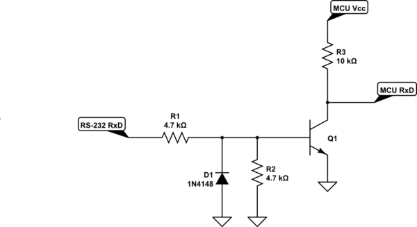
The following schematic is for a single receive function.

schematic

simulate this circuit – Schematic created using CircuitLab

I added the diode in order to protect the base of \$Q_1\$ from MARK voltages, which is what the RS-232 line typically idles at. (For older RS-232 drivers, you'd routinely see \$-12\:\text{V}\$ or \$-15\:\text{V}\$. Newer ones may be much less, now, and not quite as much of a threat to a BJT. But it is better to be safer, than sorry.)

\$\endgroup\$

Your Answer

By clicking “Post Your Answer”, you agree to our terms of service and acknowledge you have read our privacy policy.

Not the answer you're looking for? Browse other questions tagged or ask your own question.