2
\$\begingroup\$

I am designing a low profile space grade buck regulator. I have the following constraints

  1. ICs must be space grade
  2. Low component count
  3. Small size

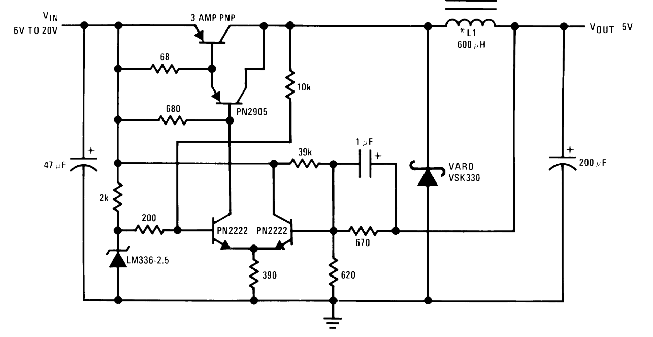
The converter specifications are as follows. Input voltage varying from 15-25V, Required outputs at 3.8V or 5.6V. I came across this converter design from an LM136 datasheet. Could someone explain the functioning of this circuit.enter image description here I can understand that there is the standard buck regulator configuration and a difference amplifier using the npn transistors. The switching functionality eludes me
\$\endgroup\$
8
  • \$\begingroup\$ Are you planning to launch it into space? \$\endgroup\$
    – winny
    Commented Jul 19, 2019 at 6:03
  • \$\begingroup\$ Well, no, not yet. The idea is to develop a small and cheap solution that can be used with other circuits to optimize the overall design \$\endgroup\$ Commented Jul 19, 2019 at 6:51
  • 10
    \$\begingroup\$ And then launch it into space? \$\endgroup\$
    – winny
    Commented Jul 19, 2019 at 6:54
  • 2
    \$\begingroup\$ LTC linecard for space grade devices: analog.com/media/en/technical-documentation/… \$\endgroup\$ Commented Jul 19, 2019 at 15:09
  • 1
    \$\begingroup\$ Even if they are radiation hardened, are you planning to launch your creation into space? \$\endgroup\$
    – winny
    Commented Jul 22, 2019 at 13:36

4 Answers 4

1
\$\begingroup\$

Pretty sure that is a hysteresis mode converter, the long tailed pair shares an emitter resistor making it a schmitt trigger and the 10k resistor just to the right of the switching devices in combination with the 200R resistor from the reference moves the threshold up and down to give the hysteresis.

There is some feed forward via the 39k resistor as well to help input side regulation.

Crude, not going to win any efficiency awards, but all discrete and fairly simple.

\$\endgroup\$
1
  • 1
    \$\begingroup\$ The emitter resistor (390 ohms just to be clear) is not what makes this a Schmitt trigger circuit. It is a simple current sink for the difference node of a differential pair. The 10 K resistor as positive feedback is what makes this circuit hysteretic. \$\endgroup\$
    – AnalogKid
    Commented Nov 24, 2020 at 13:35
2
\$\begingroup\$

It appears to be a hysteretic buck regulator. Please see link for more details. Briefly, the switch turns on if the output voltage is lower than the setpoint, and off once the output voltage rises again.

There will be an output voltage oscillation around the setpoint, so this type of regulator is not suitable for applications sensitive to some ripple. It's a cheap solution, and sounds interesting for your application.

\$\endgroup\$
1
  • \$\begingroup\$ It is expected that there would be voltage ripple around the set point. This can be reduced with an additional regulator \$\endgroup\$ Commented Jul 20, 2019 at 5:45
1
\$\begingroup\$

Take care about efficiency. The darlington PNP (PN2905 and '3 AMP PNP') has a minimum drop of 2*Vbe. You always loose about 1.5..2V at the switch! There area lot of integrated circuits that just require two external MOS-FETs, an inductor, an output capacitor and some resistors for the feedback. These chips offer better efficiency and better parameters and protection in case of overload.

I suggest you check the WEB sites of TI, Linear technology, ST Microelectronics, Maxim ... for data sheets if you need high efficiency solutions. But I have no idea which of these chips are space grade.

\$\endgroup\$
1
\$\begingroup\$

The LHS 2k resistor start the turn on the LHS PN2222, the 10k res gives turn on hysteresis.

The LHS PN2222 is on, this turns on the main xtors.

The output rises until the RHS PN2222 turns on which lifts the emitter R, turning off the LHS PN2222 as its base is fixed to 2v5.

Sometime later current flowing L to R thru the 39k and 1uF cap turns off the RHS PN2222 - as well as the o/p volts falling due to load, and the process starts again.

If the load is removed suddenly the Vout will go up a little and then the RHS PN2222 will keep the converter off until Vout falls below design - set by the res divider on the RHS PN2222 - to give 2v5 on the base = 5V out here.

\$\endgroup\$
1
  • \$\begingroup\$ Your first sentence is 84 words long, making it hard to read. Please try to clear it up. \$\endgroup\$
    – winny
    Commented Apr 17, 2021 at 8:29

Your Answer

By clicking “Post Your Answer”, you agree to our terms of service and acknowledge you have read our privacy policy.

Not the answer you're looking for? Browse other questions tagged or ask your own question.