2
\$\begingroup\$

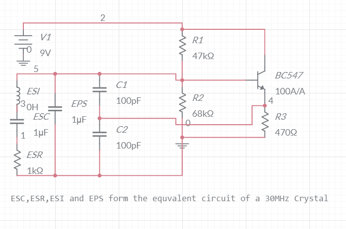
I have built this simple Crystal Oscillator circuit operating at 30Mhz and it's working fine. Please ignore the values of the equivalent circuit of the Crystal i.e ESR, EPC, ESC, ESI. I am using this circuit with an antenna at node 4 (emitter) to produce em waves which I hear as silence when I tune to 90MHz (3rd Harmonic of 30MHz)

enter image description here

What simple design should I use to modulate the frequency of the Oscillations? For example using a varactor diode. How to boost the third harmonic of the oscillations? The various circuits that I saw on the internet to do so use Inductors. Is it possible without an Inductor and a variable capacitor? I have also read this. Since inductors in 0.1uH (to get the 30Mhz resonant frequency) or less range are difficult to get if I build one on my own will it work because it's not possible to get the exact value of the inductor, So will it work even if there is a slight deviation in the inductor? Please suggest any other modifications to improve the circuit.

\$\endgroup\$
4
  • 2
    \$\begingroup\$ I dunno if it works like this, but I made a FM transmitter with an integrated oscillator. Putting an integrated buzzer next to the oscillator changed the supply voltage by a tiny tiny amount, but was sufficient to transmit a morse code type tone. It's not really that practical, could be worth a try if you want something "simple" and fun. \$\endgroup\$
    – crossroad
    Commented May 9, 2021 at 18:16
  • \$\begingroup\$ Ok, can you please explain a bit more? I can't imagine the circuit design. \$\endgroup\$
    – shahrOZe
    Commented May 9, 2021 at 18:19
  • 1
    \$\begingroup\$ You will have to adapt the circuit design since I was playing around with integrated components. Basically attach a buzzer in parallel to the oscillator power supply with a switch so that when the switch is pressed, it puts the buzzer in circuit. This exploits the fact that a lot of things are VCOs, so changing the supply voltage of the oscillator effectively modulates it. \$\endgroup\$
    – crossroad
    Commented May 9, 2021 at 18:24
  • \$\begingroup\$ Thanks but is there any other way similar to this to modulate it with audio frequency. For Example music from a phone \$\endgroup\$
    – shahrOZe
    Commented May 9, 2021 at 18:26

1 Answer 1

1
\$\begingroup\$

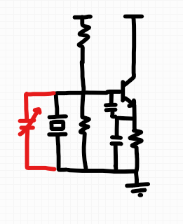
The term for what you're looking for is probably a VCXO. These exist in commercial forms, but one common arrangement is to use a variable capacitance in parallel with the crystal as follows:

enter image description here

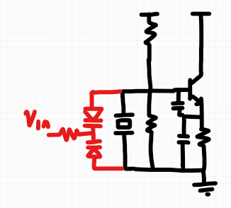
In practice, varicaps can be used; they are a diode, constructed to have a capacitance that varies with the DC bias across it. One realization described in this source uses a pair, back-to-back, to create a capacitance that varies with an applied control voltage:

enter image description here

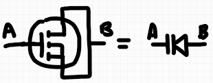
You should be able to use an off-the-shelf through-hole varicap; in a pinch, a MOSFET with source tied to drain can act as a variable capacitance between the gate and source+drain terminals:

enter image description here

There is a downside to this design however -- the additional capacitance reduces the quality-factor of the oscillator, and may introduce extra phase noise. The frequency deviation is also limited by how far the crystal itself can be pulled from its natural frequency. Instead, you may want to consider a non-crystal VCO which generates a low or intermediate frequency, and a mixer that upconverts this to your desired carrier frequency (your crystal oscillator would be the local oscillator for this arrangement).

\$\endgroup\$
2
  • \$\begingroup\$ Thanks for the answer. Will any mosfet work as a varicap? Also can i use several 1n4007 diodes in parallel to act as varicap or are there any downside to it? \$\endgroup\$
    – shahrOZe
    Commented May 9, 2021 at 20:55
  • 1
    \$\begingroup\$ I've only used on-chip integrated MOSFETs as varicaps; you may need to try a few to see how their capacitance changes with bias and whether it's in the right range. I don't think 1n4007 will work that well, although you can see the capacitance vs bias voltage on the datasheet. Honestly, the first step is probably to do some experiments to establish the range of necessary capacitance and attainable frequency deviation, and only then select a varicap or equivalent. \$\endgroup\$
    – nanofarad
    Commented May 9, 2021 at 20:58

Your Answer

By clicking “Post Your Answer”, you agree to our terms of service and acknowledge you have read our privacy policy.

Not the answer you're looking for? Browse other questions tagged or ask your own question.