I am currently working on a Buck Converter that should charge my battery pack 4S2P. The problem is that by increasing the load the voltage is dropping, and with 450 mA (depending on the value of the inductor) the voltage will completely break down.
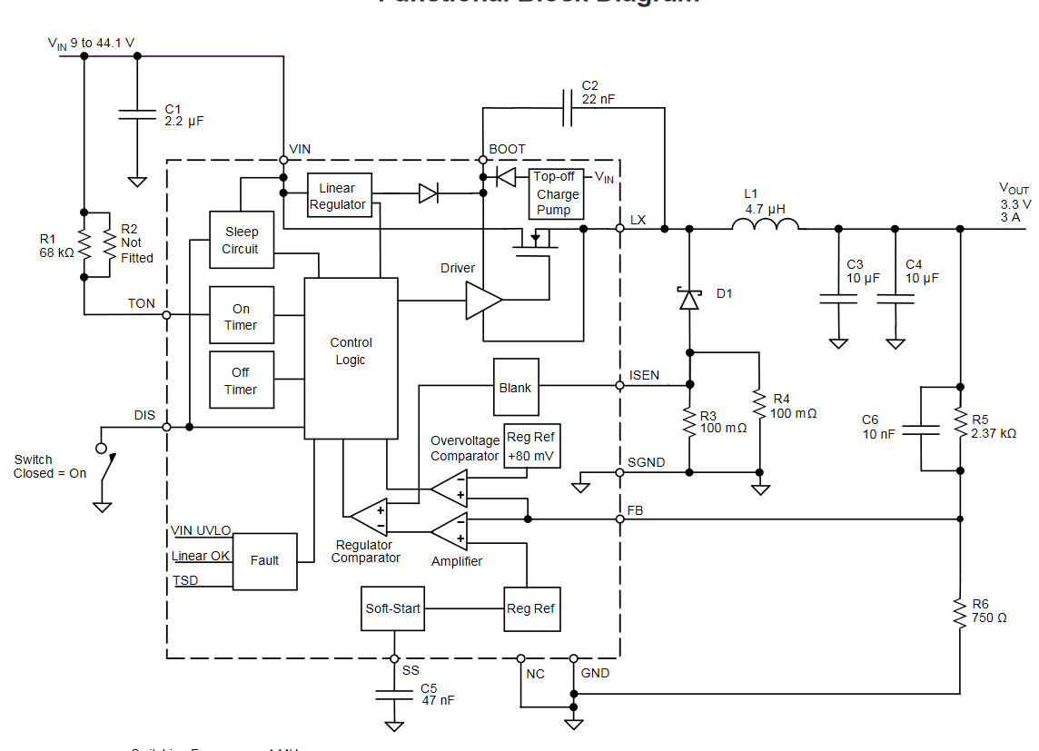
- Allegro A4403, Vin= 20VDC, Vout=16.8V, Iout,max= 1.2A
- R1 = 688k first, then I changed it to 984k.
- L1 = 10uH...86uH, higher value less load is possible
- R3=R4=110mOhm; R5=30k,R6=1k5,
- I tried different diodes, all Schottky but none worked out
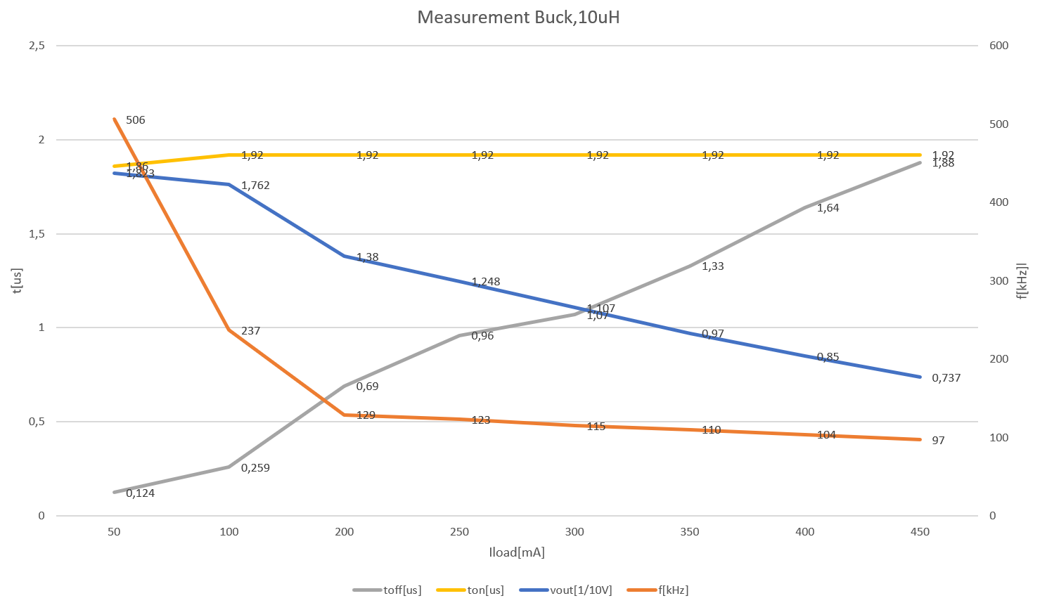
The voltage decreases as the load current increases. This is because the Toff time increases, which means the inductor cannot build up enough energy to maintain the target output voltage of 16.8V along with the increasing load current.
As the Toff time increases, the frequency decreases by the same amount, tone remains constant. Whether R1 (determines the tone time) is 1Meg or 500kOhm does not affect the maximum possible load current, but only the applied output voltage, at different load currents. Thus, the frequency is not the trigger, of the problem. With increasing inductance, the max. possible load current falls. At 10uH 450mA can flow for a short time, at 82uH less.
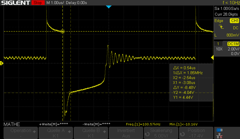
The voltage, which is applied to the current measuring resistor is deultlich too high. It is -10V for 250mA. With a current of 250mA and a current measuring resistor of 0,11Ohm only 27,5mV should flow. This is much too high and is outside the max. rating for this pin of -1.0V...0.5V. In case of doubt the device is destroyed.
Since a too high current is "measured", which should not be there, I wonder from where this comes. Some diodes were tried, which did not help. The last one was the 10MQ060N from Vishay. I have also changed the ICs which has not resulted in any change. Also I bypassed the current sense resistor and connected the diode and sense pin directly to MAsse. In doing so, I was able to measure the same waveform at the sense pin (although direser was jumpered directly to ground).
My assumption so far is that wrong diodes were installed, which passed the high voltage directly to the iSense pin, whereupon a pledge (for toff) was formed, which passed the signal directly to Isen. The feedback voltage is for the set 16.8V at 0.8V it is for the case that a very small load flows at >0.8V, because in this case the output voltage is also above 16.8V (18.9V). Again, the IC does not regulate down and there is clearly too much voltage flowing. Why it does not reduce the voltage, although the feedback voltage feeds back the correct value is a mystery to me.


