My degree had given me some electrical engineering basics, and I like to keep studying it in my spare time. I would like to achieve something with electronics, which is why I am asking here instead of programming a microprocessor for the purpose.
A component / circuit receives a voltage of 5V TTL for a time interval (e.g. two seconds). During this period, a sequence of switching the voltage on and off is to be output. An LED should flash during this period, based on the binary number 01001000 (72 in decimal), with 1 = switched on and 0 = switched off. So, I guess this 2-second period has to be divided into 8 equal steps. The number 72 is just an example.
Is there a way to achieve this with simple and “usual” components (555, operational amplifiers, comparators, MOSFETs, diodes, logic gates, flip-flops)? I ask because I use PSpice for TI2020 and I don't have every imaginable component in the libraries.
Where I stuck
I don't have the idea how to manage the start and stop times of the blinking of the LED for the different binary numbers.
Update 11/26/2021
I am pleased that my question goes down so well with you. I finished the circuit using only flip flops, gates, op amps, and 555 timers.
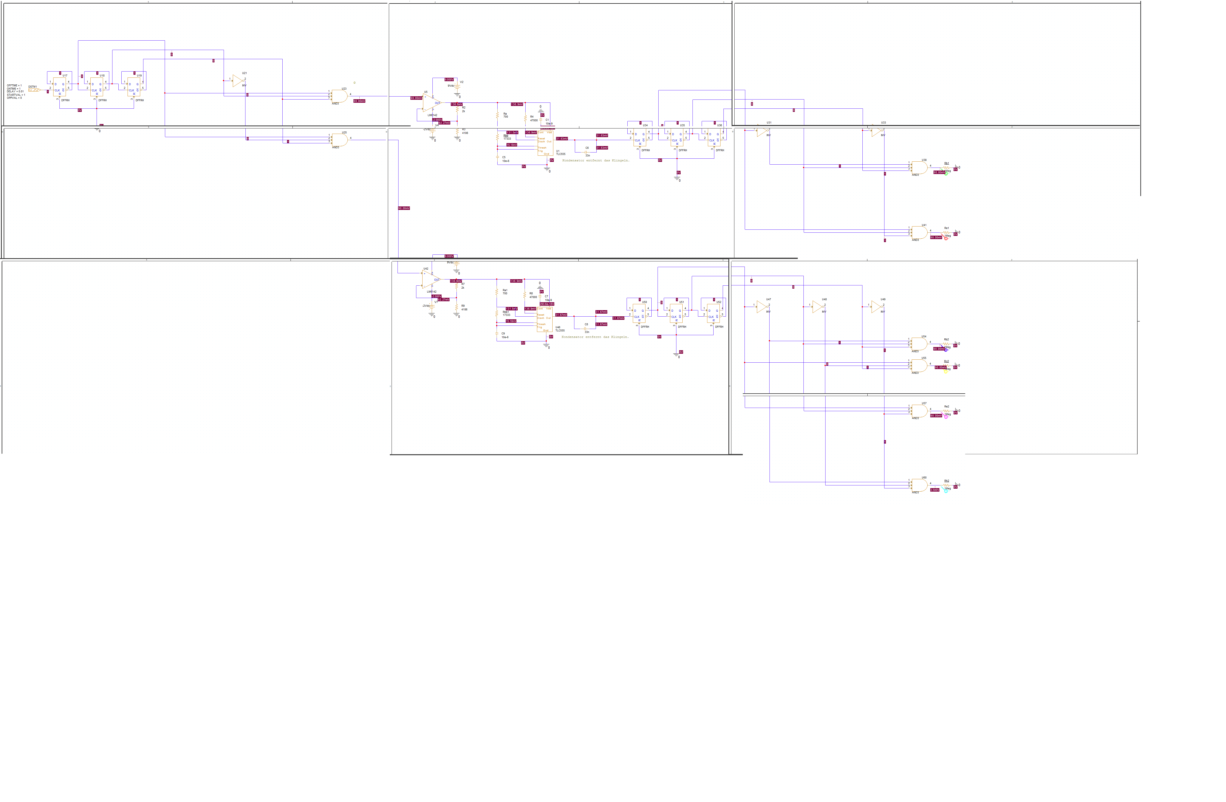
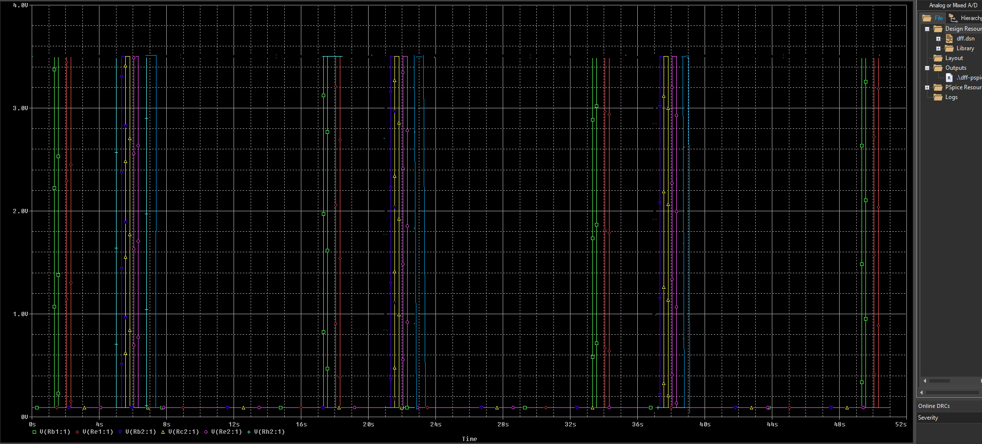
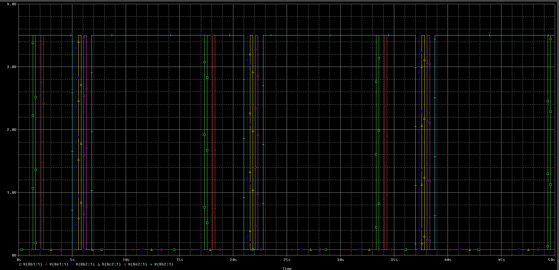
About my train of thought: In the picture, at the top left, you can see three flip-flops that count from 0 to 7, at a rate of (currently) two seconds. Since I didn't have a 3-to-8 decoder in my library, I just built and tested a decoder myself. But since I only need two exits, namely the first and the third (chosen arbitrarily), I have removed the remaining six. One output each (U23, U25) goes to an operational amplifier with a non-inverting basic circuit to increase the 3.5V to 5.2V TTL so that the timer behind it works. This means that this timer – let's take U1 as an example – receives voltage for 2 seconds. During this period, it fires 16 times. This timer shifts the next 3 flip-flops through (0–7). The outputs № 2 and № 5 emit a voltage. This is my “H” (B 0100 1000). The same thing happens in a copy further down in the picture. Except that I am using the “decoder” output № 2, № 3, № 5 and № 8 here. This pattern represents an “i” (B 0110 1001). So it should look like this in the simulation:
Unfortunately (understandably) the last state remains. That is, at the moment it looks like this:
I've already thought about simply letting the timer (U46) run a little faster, but then another state is "permanently" active. So how do I get the last output (U60) back to low, as it should actually?


